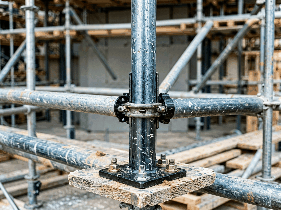
A U head base jack is a critical load-bearing component in scaffolding systems, designed to transfer vertical loads from the scaffold structure to the ground while providing precise height adjustment and lateral stability. It consists of a threaded spindle, a base plate, and a U-shaped head that engages with scaffold ledgers or transoms.
Unlike fixed base plates, the U head base jack allows incremental height adjustment through rotational movement of the spindle, enabling compensation for uneven terrain and accurate alignment of scaffold levels. The U head geometry ensures positive engagement with horizontal members, preventing lateral displacement under load.
The load capacity of a U head base jack is determined by the material yield strength, spindle diameter, thread pitch, and base plate dimensions. Standard configurations typically support axial loads between 20 kN and 36 kN per jack, depending on size and material grade, with safety factors applied per regional scaffolding standards (e.g., EN 12811, OSHA 1926 Subpart L).
Buckling resistance is influenced by the unsupported length of the spindle; longer extensions reduce critical buckling load. To maintain stability, the maximum extension should not exceed 75% of the spindle length, and the base plate must remain fully supported on compacted ground or sole plates.
U head base jacks are manufactured from structural steel grades such as S235JR or S355JR, chosen for their yield strength, weldability, and resistance to deformation under cyclic loading. The spindle is typically machined from C45 or equivalent medium-carbon steel, hardened to 20–25 HRC to resist thread wear and galling during repeated adjustment.
Base plates are stamped or cut from 6–8 mm thick steel, providing sufficient rigidity to prevent bending under eccentric loads. Surface treatments include hot-dip galvanizing (minimum 55 μm zinc coating) or electro-galvanizing for corrosion resistance, with hot-dip preferred for outdoor or humid environments.
| Parameter | Typical Range | Notes |
|---|---|---|
| Spindle Diameter | 32 mm – 38 mm | Affects load capacity and resistance to bending |
| Thread Pitch | 5 mm – 6 mm | Determines adjustment resolution per revolution |
| Base Plate Size | 120 mm × 120 mm – 150 mm × 150 mm | Larger plates reduce ground pressure on soft surfaces |
| Adjustment Range | 300 mm – 600 mm | Depends on spindle length; consult manufacturer for limits |
| U Head Width | 100 mm – 120 mm | Matches standard scaffold tube dimensions (48.3 mm OD) |
The U head width is designed to accommodate standard 48.3 mm diameter scaffold tubes with a tight fit to minimize play. The internal height of the U head typically measures 50–55 mm, providing sufficient bearing surface for the ledger while allowing for clearance during installation.
U head base jacks are primarily used at the base of independent tied scaffolds, birdcage scaffolds, and access towers where vertical load transfer and height adjustability are required. They are essential in applications involving uneven substrates, such as sloped ground, uneven concrete slabs, or temporary foundations on gravel or soil.
In facade scaffolding, they enable precise alignment of the first lift to match building contours, ensuring subsequent levels remain plumb. In shoring and formwork systems, they support vertical loads from concrete slabs or beams during curing, allowing for controlled descent during stripping.
Their use reduces reliance on timber sole plates or custom shimming, improving installation speed and consistency across large-scale projects. They are also compatible with mobile scaffolding towers when paired with lockable casters or outriggers.
To install, position the base plate on a stable, level surface or sole plate. Insert the spindle through the base plate nut, ensuring the threads engage fully. Place the scaffold ledger into the U head and secure it with a scaffold coupler or pin, depending on the system design.
Adjust height by rotating the spindle using a scaffold wrench or spanner. Clockwise rotation raises the scaffold; counterclockwise lowers it. After adjustment, verify that the spindle extends equally from both sides of the base plate nut to prevent eccentric loading.
Never exceed the manufacturer’s marked maximum extension limit. Inspect the spindle for straightness, thread damage, or corrosion before use. Ensure the base plate remains in full contact with the ground; gaps indicate instability and require re-leveling or additional sole plating.
Critical quality checks include dimensional verification of spindle diameter, thread pitch, and U head geometry using calibrated gauges. Thread integrity is assessed via go/no-go gauges to ensure proper engagement with adjusting nuts. Base plate flatness is checked to ensure uniform load distribution.
Welds (if present) connecting the spindle to the base plate nut are inspected for penetration and absence of cracks. Hot-dip galvanized coatings are tested for thickness and adhesion. Material traceability is maintained from raw steel to finished product to support recall or audit requirements.
Load testing is performed on sample batches to validate ultimate and working load capacities. Results are documented and available upon request. Manufacturing follows ISO 9001 quality management principles, with process controls for machining, threading, and surface treatment.
While standard configurations meet most scaffolding needs, customization is available for specialized applications. Spindle length can be increased to extend adjustment range beyond 600 mm for deep foundations or elevated work platforms. Base plate dimensions can be enlarged to reduce ground pressure on soft or sensitive surfaces.
Alternative thread forms (e.g., trapezoidal or ACME) may be supplied for environments requiring higher wear resistance or smoother operation under frequent adjustment. Surface treatments can include powder coating or duplex systems for enhanced corrosion resistance in aggressive environments.
U head geometry can be modified to accommodate non-standard scaffold tube sizes or integrated with adjustable swivel heads for use on sloped surfaces. All customizations are subject to engineering review to ensure load capacity and safety compliance.





