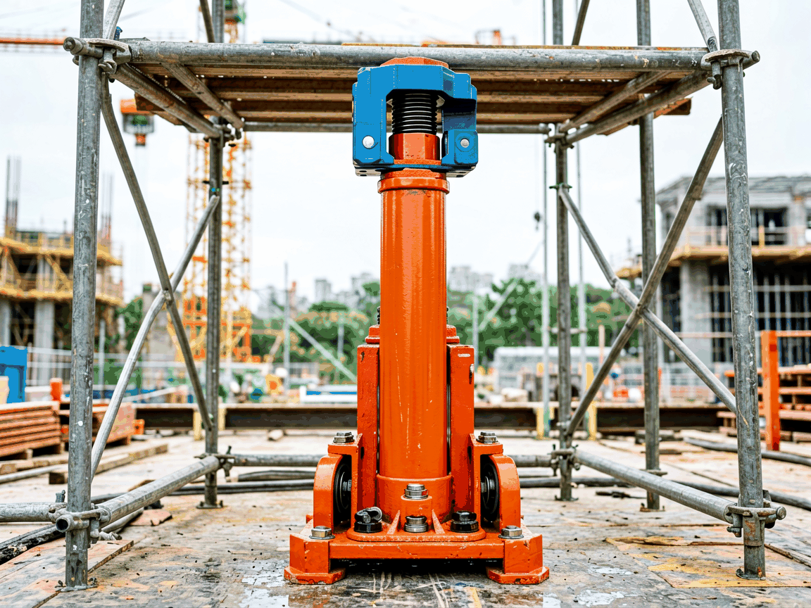
U head screw jacks are precision-engineered components used in scaffolding systems to provide adjustable vertical support and load distribution. They consist of a threaded spindle, a U-shaped head that cradles scaffold ledgers or transoms, a base plate for load transfer to the ground, and a locking mechanism to secure position. The U head design allows for quick insertion and removal of horizontal members while maintaining alignment under load. These jacks are essential for erecting stable, level working platforms on uneven terrain, where fixed-length components cannot compensate for ground variation. Their primary function is to transfer structural loads from the scaffold to the foundation while enabling fine-tuned height adjustments during assembly and dismantling.
Load capacity is determined by spindle diameter, thread pitch, material grade, and effective length under buckling constraints. Standard U head screw jacks for industrial scaffolding typically feature a 32mm or 38mm solid steel spindle with Acme or trapezoidal threading to resist wear and self-loosen under vibration. The U head is forged from structural steel plate, designed to accommodate 48.3mm or 50.8mm OD scaffold tubes with a minimum bearing surface of 50mm x 100mm to prevent localized deformation. Base plates are generally 150mm x 150mm or 200mm x 200mm square, fabricated from 6mm thick steel to distribute ground pressure below 150 kPa on compacted soil. Adjustment range varies by model, commonly 300mm to 600mm, with fine thread pitches (e.g., 6mm or 8mm) allowing approximately 1mm of lift per full spindle rotation for precise leveling.
| Parameter | Typical Value | Notes |
|---|---|---|
| Spindle Diameter | 32mm or 38mm | Solid cold-drawn steel, Grade 8.8 minimum |
| Thread Type | Trapezoidal or Acme | Self-locking under static load, resistant to back-drive |
| U Head Size | 50mm x 100mm bearing surface | Accommodates 48.3mm or 50.8mm OD scaffold tube |
| Base Plate | 150mmx150mm or 200mmx200mm | 6mm thick steel, reduces ground pressure |
| Adjustment Range | 300mm to 600mm | Dependent on spindle length and thread pitch |
| Lift per Rotation | 1mm to 1.5mm | Based on 6mm or 8mm thread pitch |
| Safe Working Load (SWL) | 20 kN to 35 kN | With 3:1 safety factor, varies by model and spindle size |
Material choice directly impacts service life, maintenance requirements, and performance in harsh environments. Spindles are typically manufactured from cold-drawn carbon steel (e.g., C45 or equivalent) hardened to 25-35 HRC to resist thread wear and deformation under cyclic loading. U heads and base plates are fabricated from structural steel grades such as S235JR or S355JR, selected for weldability and impact toughness. In environments with high moisture, chloride exposure, or industrial pollutants, hot-dip galvanization per ISO 1461 is commonly applied, providing a minimum zinc coating thickness of 55 microns for sustained protection. Alternative coatings like zinc-rich primers or duplex systems may be specified for offshore or chemical plant applications where standard galvanization is insufficient. The threaded interface is often lubricated during assembly to prevent galling and ensure consistent torque-to-load relationship throughout the jack’s service life.
Proper installation begins with site assessment to determine ground bearing capacity and required elevation. Base plates must be placed on stable, compacted surfaces; soft ground necessitates the use of timber soleplates or steel spreader beams to prevent settlement. The spindle is inserted through the U head, and the assembly is positioned vertically under the scaffold ledger. Initial height is set by rotating the spindle until the U head makes firm contact with the horizontal member, ensuring full bearing across the 50mm x 100mm surface. Locking pins or collars are then engaged to prevent accidental rotation during use. Load should be applied gradually, and alignment verified after initial loading, as minor settlement may occur. Regular inspection during use focuses on thread condition, deformation of the U head or base plate, and secure engagement of locking mechanisms. Any signs of bending, cracking, or excessive thread wear require immediate removal from service.
U head screw jacks are indispensable in scenarios where scaffold erection must adapt to uneven foundations while maintaining precise horizontal and vertical alignment. In petrochemical plants, they support access scaffolding around vessels and piping racks where concrete foundations vary due to differential settlement or embedded foundations. In bridge construction, they enable erection of falsework and formwork systems over irregular terrain or existing structures, allowing contractors to achieve the exact soffit elevation required for concrete pours. Shipyards utilize them for dry dock and hull access scaffolding, where keel blocks and floor plates create non-uniform support points. During building renovation, they facilitate facade access on historic structures with uneven footings or basement projections. The ability to make micro-adjustments under load is particularly valuable in formwork systems, where even 5mm of misalignment can affect concrete surface finish or structural tolerances.





