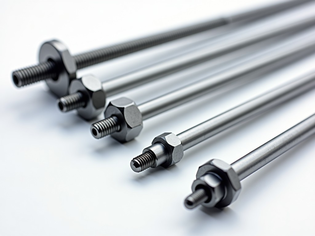
Scaffolding couplers are critical connection components that join steel tubes to form stable, load-bearing structures. Their design directly impacts structural integrity, assembly speed, and safety compliance on construction sites. Understanding the functional differences between coupler types enables engineers and procurement teams to select components that match specific load requirements, erection methods, and regulatory standards.
Couplers are primarily categorized based on how they connect scaffold tubes: right-angle, swivel, and sleeve (or pin) couplers. Each type serves a distinct geometric function in the scaffold framework, determining the angle and rigidity of the joint. The connection method influences not only the mechanical behavior under load but also the ease of installation and inspection.
Right-angle couplers connect two tubes at a precise 90-degree angle, forming the most common joint in facade and independent tied scaffolds. They consist of two half-shells that clamp around the tubes, secured by bolts or wedge mechanisms that generate frictional resistance to prevent slippage. The clamping force must exceed the expected shear load to maintain joint rigidity under dynamic conditions such as wind or worker movement.
These couplers are typically forged from carbon steel or hot-dip galvanized to resist corrosion in outdoor environments. The internal geometry features serrations or knurling to increase grip on the tube surface, reducing reliance on bolt torque alone. Standard designs accommodate tubes with outer diameters of 48.3 mm, though variants exist for 42 mm and 60.3 mm systems used in specialized applications.
Swivel couplers allow rotational adjustment between connected tubes, enabling connections at any angle from 0 to 360 degrees. This flexibility is essential for constructing complex geometries such as stair towers, curved facades, or birdcage scaffolds where fixed-angle joints would be impractical. The swivel action is achieved through a pivoting mechanism housed within a sealed casing to prevent ingress of debris and moisture.
Load transfer in swivel couplers relies on friction between the clamping elements and the tubes, similar to right-angle types, but the rotational freedom introduces additional considerations for moment resistance. Engineers must verify that the coupler’s design limits rotational play under load to prevent gradual deformation or joint loosening over time. High-strength bolts and hardened washers are commonly used to maintain clamping integrity.
Material selection mirrors that of right-angle couplers, with hot-dip galvanization being standard for corrosion protection. Some manufacturers offer stainless steel variants for use in chemically aggressive environments such as petrochemical plants or marine structures, where chloride exposure accelerates degradation of standard coatings.
Sleeve couplers, also known as pin or spigot couplers, join tubes end-to-end by inserting a tapered pin into aligned sleeves welded to each tube. This creates a rigid, axial connection ideal for vertical standards where continuity of load path is critical. Unlike clamp-type couplers, sleeve joints rely on mechanical interlock and bearing resistance rather than friction, making them less susceptible to loosening under vibration.
The pin is typically forged from alloy steel and heat-treated to achieve high shear strength, while the sleeves are formed from seamless tube stock with precise internal dimensions to ensure a tight fit. Tolerances are controlled to within ±0.2 mm to prevent excessive play or binding during installation. This precision allows sleeve couplers to maintain alignment in tall structures exceeding 30 meters in height.
Installation requires alignment of the tube ends and insertion of the pin, often assisted by a drift pin or hammer. Once in place, the joint resists both tensile and compressive forces along the tube axis. Sleeve couplers are frequently used in system scaffolding where modularity and repeatable assembly are prioritized over adaptability.
| Coupler Type | Connection Angle | Primary Use Case | Load Resistance Characteristics |
|---|---|---|---|
| Right-Angle | Fixed 90° | Facade scaffolds, independent tied scaffolds, general access | High shear resistance; relies on clamping friction; susceptible to slip if under-torqued |
| Swivel | Adjustable 0–360° | Stair towers, curved facades, birdcage scaffolds, complex geometries | Moderate moment resistance; rotational play must be controlled; depends on clamping integrity |
| Sleeve (Pin) | 0° (axial) | Vertical standards, system scaffolding, high-rise structures | High axial strength; resists tension and compression; minimal play; relies on mechanical interlock |
The majority of scaffolding couplers are manufactured from carbon steel grades such as Q235 or S235JR, chosen for their balance of strength, ductility, and weldability. Forged components exhibit superior grain flow and impact resistance compared to cast alternatives, particularly in high-stress areas like bolt holes and clamping surfaces. Heat treatment may be applied to pins and bolts to achieve target hardness levels, typically ranging from HRC 20 to 30 for wear resistance without brittleness.
Corrosion protection is achieved through hot-dip galvanizing per ISO 1461, providing a zinc coating thickness of 55–85 μm for service life exceeding 15 years in rural and urban environments. In marine or industrial zones with high sulfur or chloride exposure, duplex systems combining galvanizing with epoxy coatings or stainless steel (grades 304 or 316) may be specified. Coating integrity is verified through visual inspection and adhesion testing per ASTM D3359.
Tube compatibility is critical: couplers must match the outer diameter and wall thickness of the scaffold tube to ensure proper clamping force and prevent tube deformation. Mismatched components can lead to reduced slip resistance, localized stress concentrations, or premature failure. Manufacturers provide dimensional charts specifying compatible tube ranges for each coupler model.
Industrial buyers should verify that couplers comply with relevant standards such as EN 74, BS 1139, or ANSI/ASSE A10.8, depending on the regional market. These standards define performance requirements including slip resistance, ultimate load capacity, and dimensional tolerances. Type testing typically involves applying incremental loads to assembled joints until failure, recording the load at which slip exceeds allowable limits (usually 3 mm).
Batch testing includes hardness checks on critical components, coating thickness measurements, and dimensional verification of bores and clamping surfaces. Non-destructive methods such as magnetic particle inspection may be used to detect surface cracks in forged parts. Traceability is maintained through batch markings that link finished goods to raw material certificates and process records.
Suppliers should provide material test certificates (MTCs) and test reports upon request. Couplers lacking documented compliance with recognized standards pose significant safety risks and may invalidate insurance or regulatory approvals for scaffold structures. Procurement teams are advised to request test data as part of the qualification process.
The choice of coupler type should align with the scaffold’s geometric complexity, load conditions, and erection methodology. For simple, repetitive facades, right-angle couplers offer cost-effective and fast assembly. Swivel couplers are justified only when angular flexibility is required, as their higher cost and slightly lower rigidity must be weighed against design needs. Sleeve couplers are preferred in vertical applications where axial load transfer and joint stiffness are paramount, such as in shoring or falsework supporting concrete loads.
In high-rise construction, a combination of sleeve couplers for vertical continuity and right-angle or swivel couplers for horizontal bracing optimizes both strength and adaptability. Temporary structures like event stages or concert rigging may prioritize swivel couplers for rapid reconfiguration, even if it requires additional inspection intervals to monitor joint integrity. Environmental factors such as temperature extremes or corrosive atmospheres further influence material and coating selections.
Ultimately, the goal is to minimize on-site modification and ensure that the coupler’s performance characteristics match the design assumptions used in structural calculations. Mismatched components can lead to unforeseen deformation, increasing the risk of instability or collapse under load.





