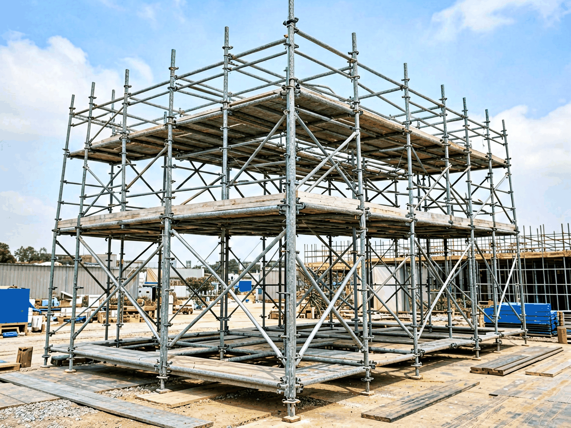
A truss rack scaffold system is a modular temporary structure designed to support personnel, materials, and equipment during construction, maintenance, and industrial operations. Unlike traditional tube-and-coupler scaffolds, it uses prefabricated truss-based frames that interlock to form rigid bays, reducing on-site assembly time and improving load distribution across uneven terrain.
The system’s primary load-bearing elements are triangular or rectangular truss frames made from cold-formed steel sections, typically with a minimum yield strength of 345 MPa. These frames transfer vertical loads through axial forces in the members rather than bending, minimizing deflection under heavy concentrated loads such as formwork or storage racks. Diagonal bracing within each truss resists lateral forces from wind or accidental impact, while horizontal ledgers at each level tie adjacent bays together to prevent racking.
Connection points use forged steel couplers with tapered pins and safety clips, designed to withstand cyclic loading without fatigue failure. Each joint is engineered to maintain rotational stiffness under service loads, reducing drift in tall configurations. The modular grid—commonly 1.5m or 2.0m bay widths—allows precise alignment with building grids or equipment layouts, reducing the need for custom cutting or shimming.
Main chords and webs are typically produced from S355JR hot-rolled or cold-formed steel, conforming to EN 10025-2 or ASTM A572 Grade 50 standards. Thickness ranges from 2.5mm to 4.0mm depending on load class and span, with corrosion protection applied via hot-dip galvanizing to a minimum coating weight of 550 g/m² (both sides) per EN ISO 1461. In aggressive environments—such as chemical plants or marine zones—optional duplex systems (galvanized plus epoxy primer) are available upon request.
All hardware components, including pins, clips, and base jacks, are manufactured from hardened steel with zinc plating or mechanical galvanizing to meet ISO 2081 standards. Base jacks feature ACME-threaded spindles with a minimum 40mm adjustment range and swivel base plates to accommodate slopes up to 5° without shimming. Swivel casters, when used for mobile towers, include dual-locking mechanisms (swivel and wheel) rated for dynamic loads of at least 10 kN per caster.
Load ratings are determined per EN 12810/12811 or equivalent local standards, with classifications based on uniformly distributed load (UDL) per bay and point load capacity at node points. A standard 2.0m bay with 2.0m height typically supports a UDL of 3.0 kN/m² (Class 3) or a concentrated load of 15 kN at mid-span of the ledger, assuming proper bracing and base support. Higher load classes (up to Class 6, 6.0 kN/m²) require closer bay spacing, increased member thickness, or additional intermediate transoms.
Maximum freestanding height is generally limited to 4 times the minimum base dimension unless tied to a structure at intervals not exceeding 8.5m vertically and 9m horizontally. For suspended or cantilevered configurations—common in facade work or overhang applications—engineer-approved calculations are required to verify anchor capacity, deflection limits, and uplift resistance. The system’s modular nature allows reconfiguration for changing site conditions without dismantling entire bays.
Assembly relies on a pin-and-clock mechanism where tapered pins are inserted through aligned coupler holes and secured with spring-loaded safety clips—eliminating the need for bolts or wrenches. A two-person crew can typically erect 20–25 m² per hour on level ground, assuming pre-staged components and clear access. Vertical erection uses integrated ladder frames or temporary stair towers built into the scaffold geometry, reducing reliance on external access equipment.
Color-coded components (e.g., red for ledgers, blue for diagonals) and numbered frames assist in correct sequencing, reducing erection errors. Disassembly follows the reverse sequence, with all components designed to nest efficiently for transport and storage. The system’s low part count—often fewer than 15 unique SKUs per bay configuration—simplifies inventory management for rental companies and contractors managing multiple sites.
Truss rack scaffolds are particularly advantageous in projects requiring repeated access to elevated work zones over extended periods, such as tank maintenance in refineries, curtain wall installation on high-rises, or conveyor system assembly in manufacturing plants. Their high stiffness-to-weight ratio makes them suitable for supporting heavy formwork during concrete pours in infrastructure projects, where deflection limits are strictly governed by concrete finish tolerances.
In power generation facilities, they provide stable platforms for boiler inspection and turbine maintenance, where thermal expansion of adjacent structures demands a scaffold that can accommodate minor movement without inducing stress concentrations. The open geometry also facilitates unobstructed crane lifts and material hoisting, reducing congestion in tight work areas compared to enclosed frame systems.
| Feature | Truss Rack System | Tube-and-Coupler | Frame System (Wedge Lock) |
|---|---|---|---|
| Assembly Speed | Fast (pin-based) | Slow (bolt-dependent) | Moderate (hammer-activated) |
| Load Capacity (Class 4 Equivalent) | High (axial load path) | Moderate (bending-dependent) | Moderate |
| Adaptability to Irregular Geometry | Good (modular bays) | Excellent (fully flexible) | Limited (fixed bay sizes) |
| Transport Volume per m² | Low (nestable frames) | High (loose components) | Moderate |
| Reusability Cycles | High (durable connections) | Moderate (thread wear) | Moderate (wedge deformation) |
While tube-and-coupler systems offer unmatched flexibility for complex geometries, they require more labor and inspection due to the high number of couplers. Frame systems provide fast erection but are limited to rectilinear layouts and may experience wedge wear over time. Truss rack systems occupy a middle ground—offering superior load efficiency and repeatability for standard grids while retaining enough adaptability for most industrial and commercial applications.
Manufacturing begins with precision cutting of steel coils to specified lengths, followed by roll-forming or pressing to create truss chords and webs with consistent dimensional tolerances (±1.5mm). Welding is performed using automated MIG or TIG processes on critical joints, with 100% visual inspection and periodic radiographic testing on sample couplers to detect porosity or incomplete fusion. All welded assemblies undergo stress-relief baking if required by material thickness or design code.
Galvanizing is performed in-house or by certified third-party baths, with coating thickness verified via magnetic induction gauges at minimum five points per component. Final assembly includes functional testing of pin insertion and clip retention under simulated load cycles. Each batch is traceable via heat number and production date, with material test certificates available upon request. Packaging uses steel straps and corner protectors to prevent deformation during transit, with components sorted by type and length for efficient site retrieval.





