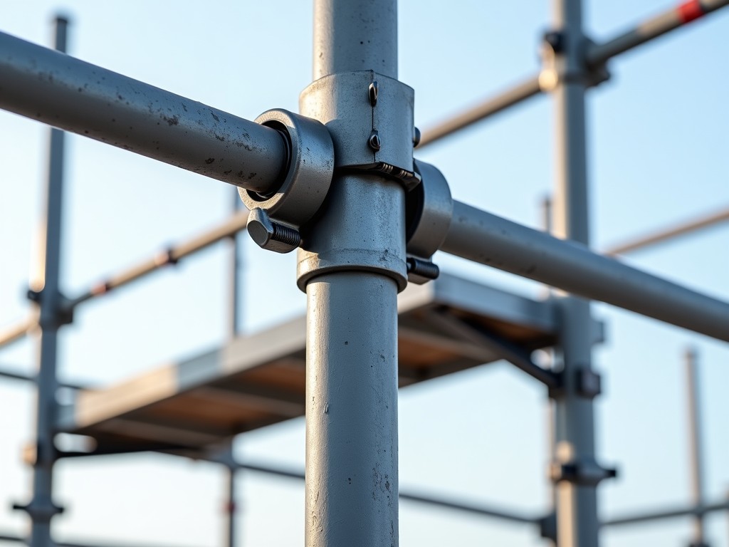
A total station column clamp is a precision mounting device designed to securely attach surveying instruments—such as total stations, laser scanners, or GNSS antennas—to vertical structural columns in construction, infrastructure, and industrial environments. Its primary function is to provide a stable, repeatable, and vibration-resistant interface that maintains instrument alignment during extended measurement sessions, ensuring data integrity in high-accuracy surveying tasks.
Unlike temporary tripod setups or improvised brackets, column clamps are engineered for semi-permanent or repeated-use installations where consistent datum points are critical. They eliminate setup variability by locking the instrument to a fixed reference on the column, reducing human error and minimizing the need for re-leveling or re-centering between shifts. This is particularly valuable in monitoring applications, deformation analysis, and long-baseline staking where millimeter-level repeatability is required.
The clamp mechanism typically employs a split-ring or C-frame design that wraps around the column, tightened via threaded fasteners or eccentric cam systems to generate uniform radial pressure. This distributes clamping force evenly to avoid point loading that could deform slender columns or damage protective coatings. Surface contact is often enhanced with interchangeable pads—made from nylon, urethane, or rubber—to accommodate different column materials (steel, concrete, timber, or composite) without marring or slipping.
Load capacity is determined by the clamp’s cross-sectional geometry, bolt grade, and friction interface. Most models are rated to resist overturning moments exceeding 50 Nm under dynamic loads, sufficient to withstand wind gusts, minor impacts, or cable tension from attached data loggers or power supplies. The clamping force is adjustable, typically ranging from 2 kN to 8 kN, allowing optimization based on column diameter and material hardness to prevent over-compression or insufficient grip.
Angular adjustment ranges vary by model but commonly include ±5° tilt and 360° azimuth rotation, enabling fine alignment of the instrument’s vertical axis with the column’s centerline. This adjustability compensates for column out-of-plumb conditions frequently encountered in existing structures. Some designs incorporate vernier scales or micrometer screws for sub-millimeter positional refinement, critical when establishing control networks tied to structural grids.
Materials are selected for environmental durability and dimensional stability. The main frame is usually constructed from extruded or machined aluminum alloy (e.g., 6061-T6) for its strength-to-weight ratio and corrosion resistance, though stainless steel (304 or 316) variants are available for harsh chemical or marine environments. Fasteners are typically grade 8.8 or A2-70 stainless steel to prevent galling and ensure consistent torque retention over time.
In building information modeling (BIM) workflows, column clamps support the placement of total stations for as-built verification against digital models. By fixing the instrument to a known column grid point, surveyors can efficiently collect point clouds or prism measurements for clash detection and progress tracking. The repeatability of the mount reduces the uncertainty in coordinate transformation between local survey control and the BIM origin, improving the reliability of deviation reports.
For deformation monitoring of bridges, towers, or retaining walls, clamps enable long-term installation of total stations or automated motorized systems. Unlike tripods, which require daily setup and are susceptible to thermal drift or settlement, a clamped mount maintains a fixed exterior orientation relative to the structure. This allows differential measurements to isolate true structural movement from instrument instability, a key requirement in ISO 17123-6 compliant monitoring protocols.
In industrial settings—such as power plants, refineries, or manufacturing facilities—column clamps are used to mount laser trackers or photogrammetry systems for alignment of heavy machinery or piping systems. The ability to quickly reposition the clamp to adjacent columns facilitates multi-point measurement campaigns without re-establishing control networks each time. Non-marring pads are essential here to preserve protective coatings on structural steel or insulated cladding.
Clamp diameter range is a primary specification, with standard models accommodating columns from 100 mm to 600 mm outer diameter. Split-hinge designs allow installation without sliding the clamp over the column end, enabling retrofitting on active structures. Custom ranges outside these limits—such as for small-diameter poles (<80 mm) or large-diameter piers (>800 mm)—are feasible through modified frame geometry or segmented designs, though these may affect load distribution and require engineering review.
Interface plates vary to suit different instrument bases. Common options include 5/8"-11 threaded studs (matching most total station tribrachs), flat plates with M6/M8 threaded holes for adapters, or dovetail slots for quick-release systems. Some models integrate bubble vials or optical targets directly into the clamp body to aid in initial leveling or as-built documentation. Custom plates can be engineered to match proprietary instrument mounting patterns upon request.
Surface protection options include anodized aluminum (Type II or III), powder coating (epoxy or polyester), or passivated stainless steel finishes. For applications involving electrical isolation—such as when mounting GNSS receivers near power lines—nylon or PTFE liners can be inserted between the clamp and column to prevent current transfer. All materials are selected to avoid galvanic corrosion when in contact with dissimilar metals.
| Parameter | Typical Range / Option | Notes |
|---|---|---|
| Clamp Diameter Range | 100 mm – 600 mm | Custom sizes available |
| Clamping Force | 2 kN – 8 kN | Adjustable via torque |
| Angular Adjustment | ±5° tilt, 360° rotation | With vernier options |
| Frame Material | Aluminum 6061-T6 / SS 304/316 | Environment-dependent |
| Interface Type | 5/8"-11 stud, flat plate, dovetail | Custom adapters possible |
| Surface Protection | Anodized, powder coat, passivated | Non-marring pads included |
Installation requires only basic tools—typically a hex key or wrench—to tighten the clamping bolts to the specified torque. Over-tightening must be avoided, especially on thin-walled or composite columns, to prevent ovalization or stress cracking. Manufacturers provide torque guidelines based on column material and wall thickness; following these ensures optimal grip without damaging the substrate. Periodic inspection of fasteners and contact pads is recommended in high-vibration or corrosive environments to maintain performance.
When selecting a column clamp, evaluate the total system stiffness, not just the clamp itself. The column’s own flexural response under load contributes to the overall measurement uncertainty. For high-precision applications, supplemental bracing or selection of a stiffer mounting location (e.g., near column splices or brackets) may be necessary to achieve desired stability. Consulting with a metrology engineer during planning helps avoid overlooking these secondary effects.
For project-specific configurations, including custom diameter ranges, specialized interface plates, or material certifications (e.g., NACE, ISO 9001 traceability), contact our technical team with your column specifications, instrument model, and environmental conditions. We provide detailed load calculations, installation drawings, and material test reports upon request to support engineering review and procurement decisions.





