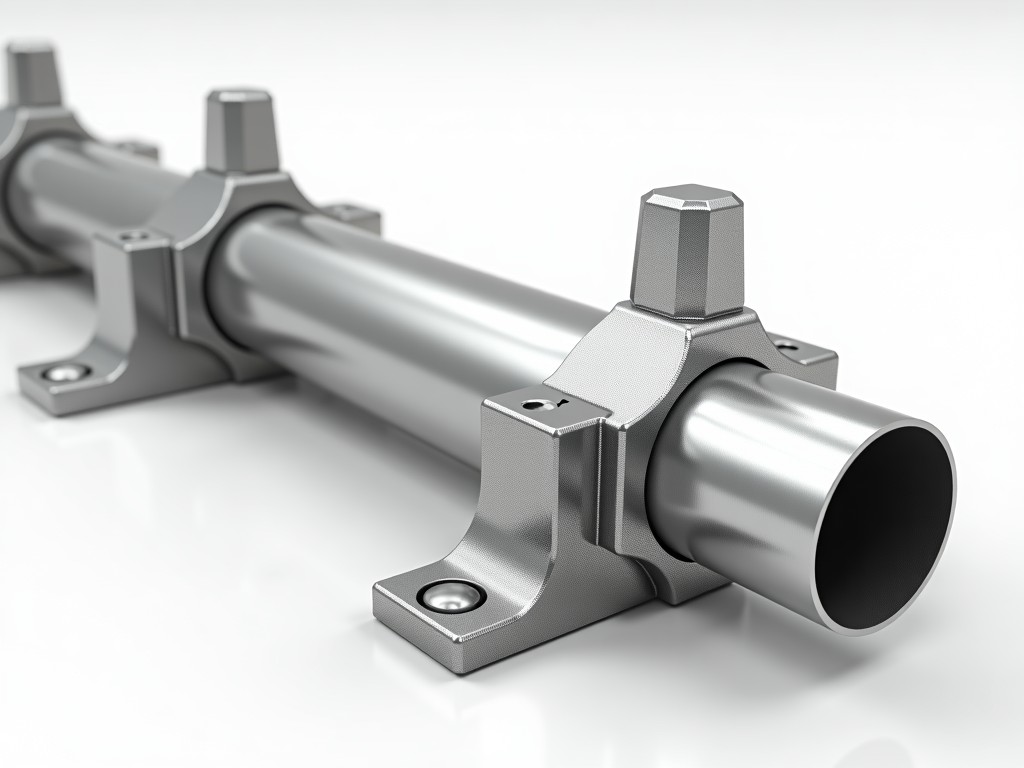
Tube and clamp scaffolding systems are engineered modular structures formed by connecting steel tubes with adjustable clamps, enabling rapid assembly of temporary support frameworks for construction, maintenance, and industrial access applications. Unlike prefabricated frame systems, tube and clamp scaffolding offers unrestricted geometric flexibility, allowing configuration to complex façades, curved surfaces, and irregular work zones where standard bay dimensions are impractical.
The system relies on high-strength steel tubing, typically 48.3mm outer diameter with 3.2mm or 4.0mm wall thickness, joined by forged or pressed steel clamps that transmit loads through friction and mechanical interlock. Clamp types include right-angle couplers for 90° connections, swivel couplers for variable angles, and sleeve couplers for end-to-end tube extension, each designed to resist slip, torsion, and tensile forces under specified working loads.
Load capacity is determined by tube grade, clamp design, and assembly configuration, with typical allowable working loads ranging from 2.2 kN to 3.6 kN per coupler depending on orientation and load direction, as defined by regional standards such as EN 74, BS 1139, or ANSI/ASSE A10.8. System stiffness and stability depend on proper bracing, base plate distribution, and tie-in frequency to structural elements, which must be calculated per project-specific engineering review.
Tube material is predominantly hot-rolled or cold-formed structural steel, commonly grades S235JR or S355JR, offering yield strengths between 235 MPa and 355 MPa with consistent elongation properties for ductile behavior under overload. Surface treatment options include hot-dip galvanizing (minimum 55µm zinc coating per EN ISO 1461) for corrosion resistance in outdoor environments, or powder coating for aesthetic and chemical resistance requirements in specific industrial settings.
Clamp bodies are typically manufactured from drop-forged steel or high-tensile pressed steel, with hardened locking mechanisms (pins, bolts, or wedges) designed to maintain clamping force under cyclic loading. Standard coupler proof loads exceed 22 kN, with ultimate tensile strength typically above 36 kN, providing a minimum safety factor of 3:1 against failure under working load conditions as required by international scaffolding standards.
Modularity is achieved through tube lengths ranging from 0.5m to 6.0m in 0.5m increments, enabling precise height and bay adjustments without cutting on-site. The system accommodates diagonal bracing, putlogs, transoms, and guardrails using the same tube and clamp components, reducing part variety and simplifying inventory management for rental fleets and long-term project stocks.
Tube and clamp scaffolding is particularly advantageous in petrochemical plant maintenance where equipment geometry, piping racks, and vessel contours require non-standard access platforms that cannot be accommodated by fixed-bay systems. The ability to erect scaffolding around spherical tanks, heat exchangers, and flare stacks with precise contour following reduces the need for custom fabrication and minimizes erection time during turnaround schedules.
In shipbuilding and marine repair, the system supports hull inspection, blasting, and painting operations on curved surfaces and complex superstructures, where adjustable clamps allow tubes to follow frame curvature and deck cambers without gaps or overhangs. Corrosion-resistant galvanized finishes are essential in saltwater environments, and the system’s drainability prevents water retention in tube joints.
For historical building restoration, tube and clamp scaffolding enables minimal visual impact and non-invasive erection, as clamps can be positioned to avoid ornamental masonry, and load distribution can be tuned via base plate spacing and tie-in points to prevent point loading on fragile façades. The system’s adaptability allows erection around cornices, arches, and spires where modular frame scaffolding would require extensive bridging or cantilevering.
| Component | Typical Specification | Optional Variants |
|---|---|---|
| Steel Tube | 48.3mm OD × 3.2mm or 4.0mm wall, S235JR/S355JR | Hot-dip galvanized, powder-coated (RAL colors), stainless steel (304/316) |
| Right-Angle Coupler | Forged steel, proof load 22 kN, slip resistance >15 kN | Quick-release pin, bolt-tightened, swivel-compatible base |
| Swivel Coupler | 360° rotation, locked at 7.5° increments, proof load 20 kN | Maintenance-free bushings, high-visibility locking collars |
| Sleeve Coupler | Internal expansion type, 150mm overlap, torque-controlled | Pin-aligned, tapered sleeve, internal ribbed for anti-rotation |
| Base Plate | 150mm × 150mm × 6mm steel, with adjustable spindle | Swivel base for slopes, U-head for beam support, cast iron spindle nut |
*Values represent typical industry configurations. Actual specifications vary by manufacturer, regional standard, and project engineering requirements. Custom lengths, coatings, and clamp designs are available upon request.
Tube straightness is verified per EN 10220, with maximum deviation not exceeding 2mm per meter for structural use. Wall thickness uniformity is monitored via ultrasonic testing at production, ensuring consistent load-bearing capacity across all lengths. Tube ends are deburred and chamfered to prevent clamp seating interference and reduce stress concentrations during insertion.
Clamp assemblies undergo batch testing for slip resistance under simulated working loads, with dynamic cycling to assess locking mechanism fatigue over 5,000 load cycles. Galvan coating thickness is measured via magnetic induction per EN ISO 1460, with adhesion tested via knife method per ASTM D3359 to ensure coating integrity during handling and erection.
Final assembly validation includes torque verification of clamp fasteners using calibrated wrenches, with installation torque values documented per coupler type (typically 50–70 Nm for bolted couplers). Load testing of sample bays to 1.5× working load is performed upon request for critical applications, with deflection and residual deformation recorded to confirm elastic behavior within limits.
When specifying tube and clamp scaffolding, project engineers must define load classes (e.g., LC1 to LC6 per EN 12810), required height, bay dimensions, and tie-in frequency based on façade wind loading and structural capacity. Clamp type selection depends on connection geometry: right-angle couplers for orthogonal grids, swivel couplers for diagonal bracing and complex junctions, and sleeve couplers for longitudinal extensions where axial alignment is critical.
Logistics planning should account for tube nesting efficiency—standard 6m tubes bundle in hexagonal packs of 19 or 37 units, optimizing container utilization. Clamp weights range from 1.2kg to 2.8kg per unit, influencing handling equipment requirements and manual handling risk assessments. On-site storage requires dry, level conditions with tube racks to prevent bending and clamp containers to avoid pin deformation.
Lead times for standard galvanized components typically range from 2–4 weeks for stock items, while custom lengths, coatings, or non-standard clamp designs may extend to 6–8 weeks depending on raw material availability and production scheduling. Export shipments require corrosion-inhibiting interlayer paper, desiccant packs, and waterproof wrapping for marine transit, with fumigation certificates available for wood pallets if required.
For technical inquiries, custom configurations, or project-specific quotations, contact our engineering team to discuss load requirements, site constraints, and delivery schedules.
Request Technical Specification




