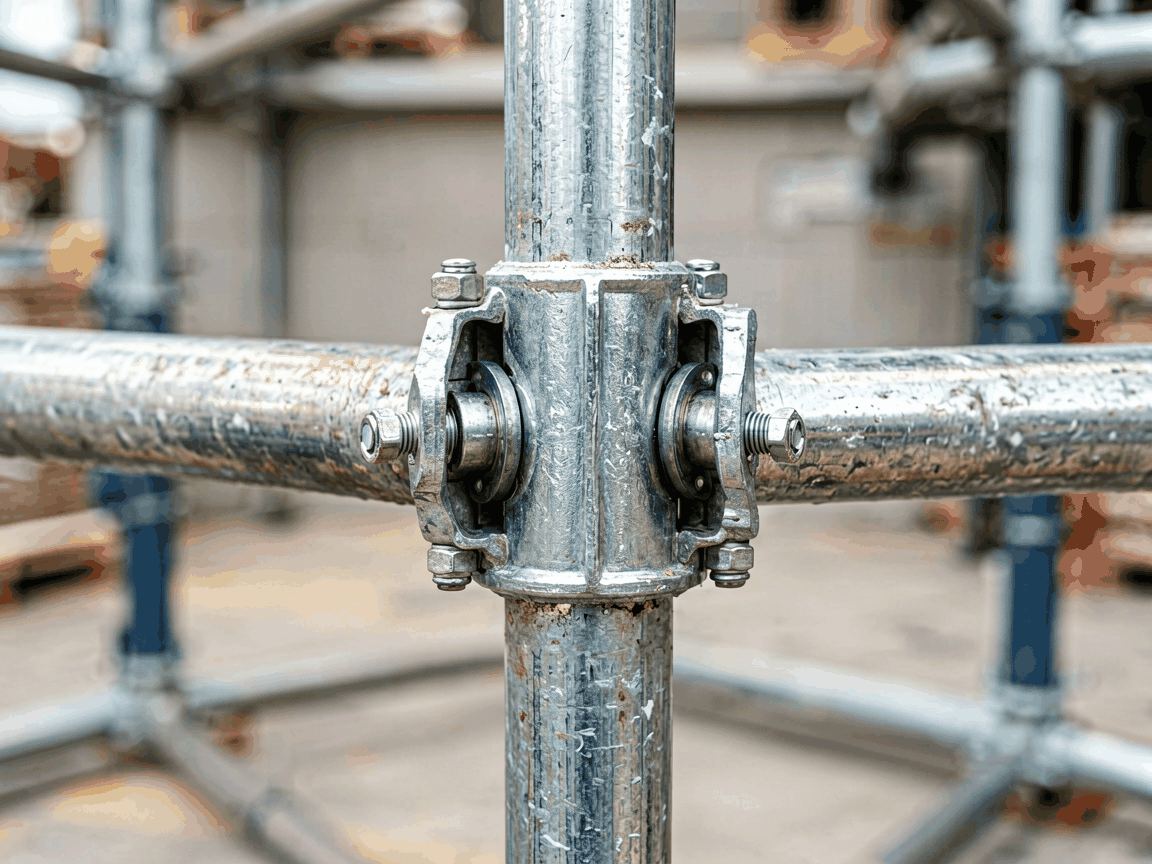
Swivel girder scaffolding couplers are mechanical fittings designed to connect scaffolding tubes to structural steel girders at variable angles. Unlike fixed-angle couplers, they allow rotational adjustment to accommodate non-perpendicular connections, which is essential when attaching temporary work platforms to irregular or sloped steel frameworks. This adaptability reduces the need for custom-fabricated brackets and minimizes field modifications during erection.
The coupler consists of a U-shaped body that grips the girder flange, a swivel mechanism enabling 360-degree rotation, and a saddle or clamp that secures the scaffolding tube. Load transfer occurs through bearing surfaces on the girder flange and the tube wall, with the swivel pin resisting rotational slip under lateral forces. The design ensures that axial, shear, and moment loads from the scaffold are distributed into the girder’s flange and web without inducing localized stress concentrations.
Material selection typically involves drop-forged or cast steel grades such as S355JR or equivalent, chosen for their yield strength and ductility under cyclic loading. The swivel pin is often hardened to resist wear, while the gripping surfaces may feature serrations or knurling to enhance frictional resistance against slip. Corrosion protection is commonly achieved through hot-dip galvanizing per ISO 1461, providing a minimum zinc coating thickness of 55 μm for exterior use.
The swivel mechanism allows the coupler to be set at any angle between 0° and 180° relative to the girder axis, enabling connections on sloped beams, tapered girders, or complex steel geometries. However, the effective load capacity may vary with angle due to changes in bearing area and load eccentricity. Manufacturers typically provide load rating charts indicating safe working loads at 0°, 45°, 90°, and 135° orientations, with derating factors applied beyond 90°.
Installation requires access to both the girder flange and the scaffolding tube. Clearance must be verified to ensure the coupler body does not interfere with stiffeners, plates, or adjacent structural components. Torque specifications for the clamping bolts—usually M16 or M20 grade 8.8—are critical; under-torquing risks slip, while over-torquing can deform the girder flange or strip threads. A torque wrench calibrated to the manufacturer’s specified value (typically 150–200 Nm for M16) is recommended.
While carbon steel is standard, alternative materials are available for specific environments. Stainless steel grades like 304 or 316L are used in corrosive atmospheres such as chemical plants or marine zones, where galvanizing may insufficiently resist chloride-induced degradation. For applications requiring non-sparking properties—such as in oil and gas refineries—aluminum bronze or copper alloy variants may be specified, though these exhibit lower strength and require larger cross-sections to compensate.
Surface treatments beyond galvanizing include epoxy powder coating for added chemical resistance or duplex systems (galvanizing plus paint) in high-humidity industrial settings. The choice of finish affects not only corrosion life but also friction characteristics at the clamping interface; some coatings may require increased bolt torque to achieve equivalent clamping force compared to bare metal.
Swivel girder couplers are frequently employed in petrochemical plant turnarounds, where scaffolding must be erected around live process units with limited access and non-standard steel geometries. Their ability to attach to sloped pipe rack girders or inclined vessel support structures eliminates the need for time-consuming custom brackets. In power generation facilities, they facilitate access platforms on boiler superstructures and turbine halls where beam orientations vary significantly across elevations.
In shipbuilding and offshore module fabrication, these couplers allow rapid erection of staging around curved hull sections or tilted block assemblies. The adjustability accommodates the inherent curvature of ship frames and the variable angles of stiffeners and longitudinals. Similarly, in bridge construction and rehabilitation, they enable suspended work platforms to be tied to main girders, cross-frames, or stringers without penetrating the structural members or compromising coating integrity.
Manufacturing quality begins with material traceability, requiring mill test reports for all raw steel used in forging or casting. Dimensional inspections verify critical features such as girder grip width, tube saddle diameter, and swivel pin clearance against drawing tolerances—typically ±0.5 mm for machined surfaces and ±1.0 mm for forged components. Load testing is performed on sample units using calibrated hydraulic actuators to simulate ultimate load conditions, with acceptance criteria based on no visible deformation, permanent set, or slip at designated proof loads.
Non-destructive testing methods such as magnetic particle inspection (MPI) or dye penetrant testing (PT) are commonly applied to high-stress areas like the swivel pin hole and clamp corners to detect surface-breaking cracks. For galvanized products, coating thickness is verified using magnetic or eddy current gauges at multiple points per ASTM A123. Batch-level documentation, including test reports and inspection records, is typically retained for traceability and provided upon request.
| Feature | Swivel Girder Coupler | Fixed-Angle Girder Coupler (90°) |
|---|---|---|
| Adjustment Range | 0°–180° | Fixed (typically 90°) |
| Installation Flexibility | High—adapts to variable girder angles | Limited—requires perpendicular girder access |
| Field Modification Need | Low—reduces need for brackets | Higher—may require adapters on non-standard angles |
| Load Capacity at 90° | Comparable to fixed type | Baseline rating |
| Load Capacity at 45° | Derated (typically 70–80% of 90° value) | Not designed for use |
| Typical Use Case | Sloped beams, complex geometries, variable access | Standard orthogonal connections |
This comparison highlights that while fixed-angle couplers offer simplicity and maximum efficiency at their design angle, swivel couplers provide essential versatility at the cost of reduced load capacity in off-axis orientations. The decision between the two depends on the geometric complexity of the host structure and the frequency of reconfiguration during the project lifecycle. In environments with consistent, perpendicular access, fixed couplers may be preferable; where geometry varies, swivel units reduce overall system complexity.
Standard swivel girder couplers accommodate scaffolding tubes of 48.3 mm outer diameter, but versions for 42.4 mm, 60.3 mm, or other sizes are available upon request to match regional scaffolding systems. Grip width can be adjusted to fit flange thicknesses ranging from 8 mm to 25 mm as standard, with wider bodies or shims available for larger sections such as H-piles or built-up girders.
For applications requiring frequent angle changes—such as in adjustable formwork or moving gantries—some models incorporate locking mechanisms with calibrated detents or worm gears to maintain position under vibration. In high-temperature environments, such as near furnaces or heat exchangers, heat-resistant alloys or thermal shields may be integrated to preserve mechanical properties. All customizations are subject to engineering review to ensure load path integrity and compliance with temporary works design standards.
To receive a quotation or technical datasheet, project teams should provide: the scaffolding tube outer diameter, girder flange width and thickness, expected load conditions (axial, shear, moment), required corrosion protection level, and any dimensional constraints such as nearby obstructions or clearance limits. Including a sketch or photo of the connection point significantly accelerates the review process.
Lead times typically range from 2 to 4 weeks for standard configurations, depending on material availability and order volume. Custom designs or special materials may extend this timeline. Samples or prototype units can be arranged for validation projects, particularly when the coupler will be used in safety-critical access systems. All inquiries are reviewed by application engineers who verify suitability against the provided parameters before confirming fitness for purpose.
For technical assistance, customization requests, or to discuss your specific scaffolding connection requirements, please contact our engineering team.
Contact Us




