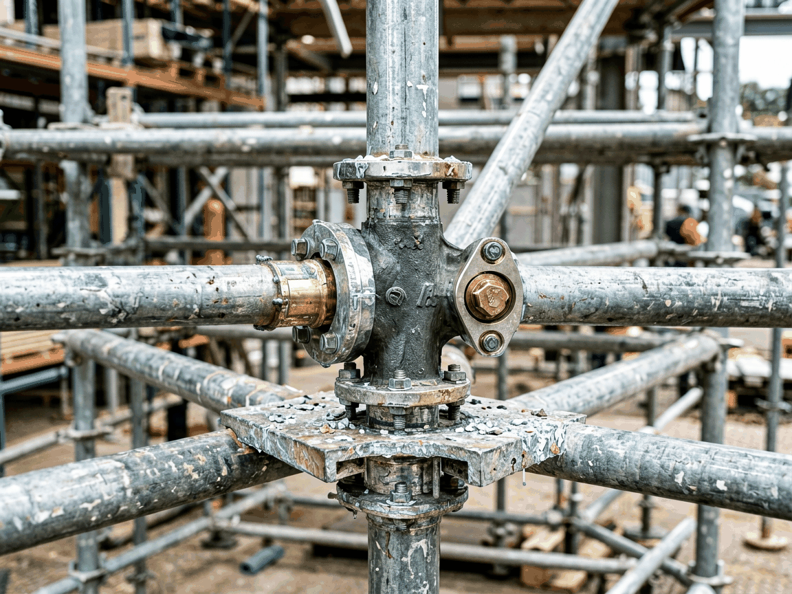
A swivel double scaffolding coupler is a critical connection component designed to join two scaffold tubes at variable angles while maintaining structural integrity under load. Unlike fixed-angle couplers, its swivel mechanism allows rotational adjustment between 0° and 360°, enabling precise alignment in complex scaffolding geometries where tubes intersect at non-standard angles. This adaptability reduces the need for custom-fabricated brackets or tube cutting, preserving modularity and accelerating erection on irregular structures such as curved facades, tanks, or industrial equipment.
The coupler consists of two forged steel jaws, each designed to grip a 48.3mm outer diameter scaffold tube, connected via a central pivot bolt that enables rotational movement. When tightened, the jaws apply radial clamping force through serrated contact surfaces, generating friction that resists both axial slip and rotational movement under load. The swivel function does not compromise load-bearing capacity because the pivot axis is engineered to align with the resultant force vector in typical bracing configurations, ensuring that shear and tensile loads are transferred directly through the clamping interface rather than the bolt itself.
Load testing per EN 74-1 shows that properly installed swivel double couplers maintain a characteristic resistance of at least 6.25 kN in tension and 30 kN in compression when used with Grade 43 scaffold tubes. The design avoids stress concentrations at the pivot point by distributing clamping force across a minimum 25mm contact length per jaw, preventing localized deformation that could lead to premature fatigue. This distinguishes it from lower-quality variants where the pivot bolt becomes a failure point under cyclic loading.
Standard production uses hot-forged S355JR steel for the jaws and pivot components, selected for its yield strength of 355 MPa and toughness at temperatures down to -20°C, suitable for most temperate and continental climates. The forged grain flow follows the contour of the jaw geometry, enhancing resistance to crack propagation under repeated loading compared to machined or cast alternatives. Surface treatment involves hot-dip galvanizing to a minimum coating thickness of 55µm, providing sacrificial protection that exceeds the 50µm requirement in EN ISO 1461 for scaffold fittings.
For environments with higher chloride exposure—such as coastal regions or chemical processing plants—alternative materials include hot-dip galvanized S355J2W (weathering steel) or duplex stainless steel (e.g., 1.4462) upon request. These options are not standard due to cost and availability but are engineered to maintain dimensional compatibility and mechanical performance while extending service life in corrosive atmospheres. Zinc-rich primers or powder coating are not recommended as primary protection for load-bearing couplers due to potential coating damage during installation and inconsistent thickness control.
The coupler is designed exclusively for 48.3mm OD scaffold tubes with a wall thickness tolerance of 3.2mm ±0.3mm, aligning with the most common international scaffolding systems (e.g., BS 1139, EN 74). Internal jaw dimensions are precision-forged to 50.5mm ±0.2mm to allow smooth insertion while ensuring sufficient interference for slip resistance when the clamping bolts are torqued to 50 Nm. Using tubes outside this range—such as 42mm or 60mm OD—compromises grip and is strictly prohibited, as it reduces contact pressure and increases the risk of sudden disengagement.
Installation requires two M12x70mm high-tensile bolts (grade 8.8) with matching nuts and washers. Torque must be applied incrementally and alternately to both bolts using a calibrated wrench to ensure even jaw closure. Over-torquing beyond 65 Nm risks thread stripping or jaw deformation, while under-torquing below 40 Nm reduces slip resistance by up to 60%. A visual inspection gap of no more than 0.5mm between the jaw faces after tightening confirms proper engagement; larger gaps indicate tube ovality, debris, or incorrect tube size.
Swivel double couplers are indispensable in scaffolding projects where tubular members intersect at angles other than 90°, such as in the construction of spherical tanks, heat exchanger bundles, or curved architectural cladding. For example, when erecting access scaffolding around a cylindrical vessel with a 5m diameter, the angle between longitudinal and circumferential tubes varies continuously; fixed couplers would require numerous bespoke brackets, increasing cost and lead time. The swivel coupler allows workers to adjust the angle on-site using only standard tubes, reducing material waste and eliminating delays associated with off-site fabrication.
In maintenance turnarounds at refineries or power plants, these couplers enable rapid reconfiguration of scaffolding around piping racks, valve manifolds, or turbine casings where obstructions prevent orthogonal layouts. Their ability to lock at any angle also supports temporary stair towers or ramps that must adapt to uneven ground or existing equipment foundations. Unlike couplers relying on friction alone, the positive mechanical lock of the swivel mechanism prevents gradual drift under vibration—a critical factor in environments with nearby rotating machinery or pulsed hydraulic systems.
Each batch undergoes dimensional verification of jaw bore diameter, pivot bolt hole alignment, and serration depth using calibrated gauges traceable to national standards. Mechanical proof testing is conducted on a statistically significant sample per batch, applying incremental tensile and compressive loads until deformation exceeds 1mm or slip occurs; results are recorded and retained for traceability. Visual inspection checks for forging laps, cracks, or incomplete galvanization under 10x magnification, with any surface defect exceeding 0.1mm depth resulting in rejection.
Batch numbers are laser-etched onto the non-load-bearing side of each coupler, linking to material certificates, test reports, and production records. This traceability supports compliance with ISO 9001 and facilitates root-cause analysis if field performance deviates from expectations. Unlike products relying solely on spot checks, this systematic approach ensures consistency across high-volume production runs while identifying process drift before it affects multiple units.
| Parameter | Typical Value | Notes |
|---|---|---|
| Tube Compatibility | 48.3mm OD | Wall thickness 2.9–3.6mm |
| Clamping Bolt Torque | 50 Nm | Grade 8.8 M12, alternate tightening |
| Tensile Resistance (Characteristic) | 6.25 kN | Per EN 74-1, Grade 43 tube |
| Compressive Resistance | 30 kN | No buckling observed in test |
| Galvanizing Thickness | ≥55µm | Hot-dip, EN ISO 1461 compliant |
| Adjustment Range | 0°–360° | Continuous, lockable at any angle |
| Operating Temperature | -20°C to +80°C | Standard S355JR steel |
Standard swivel double couplers are supplied in cartons of 50 units, each unit individually labeled with batch number and size. Bulk packaging options include palletized boxes of 400 units or wire-bound bundles of 100 for high-volume projects, all designed to prevent surface abrasion during transit. Customization is limited to material substitutions (e.g., stainless steel, weathering steel) and alternative bolt lengths for non-standard tube thicknesses; dimensional changes to the jaw geometry or pivot mechanism are not offered, as they would invalidate the product’s certified performance characteristics.
Quotations require confirmation of tube specifications (OD, wall thickness, material), required quantity, delivery timeline, and any special material or packaging requests. Lead time for standard galvanized units is typically 3–4 weeks from order confirmation, depending on raw material availability and production scheduling. Samples are available upon request for qualification testing, subject to return or purchase agreement; free samples are not provided due to the product’s load-bearing nature and associated liability.





