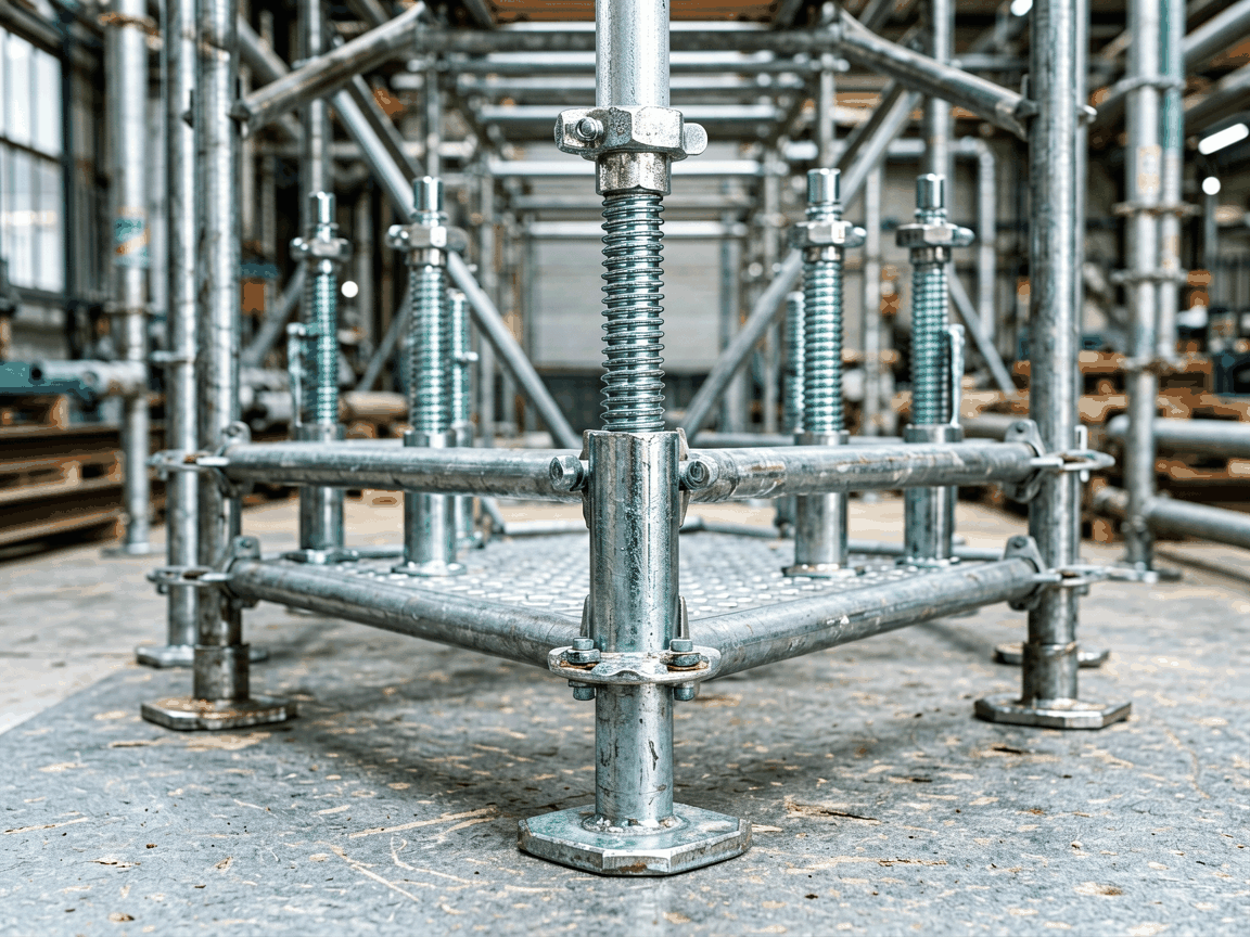
Screw jacks are fundamental components in temporary support systems, providing precise vertical adjustment and load distribution in scaffolding structures. Their function is to compensate for uneven ground, maintain structural alignment, and transfer vertical loads from the scaffold to the foundation.
Unlike fixed base plates, screw jacks incorporate a threaded mechanism that allows incremental height adjustment—typically ranging from 200 mm to 600 mm of travel—enabling installers to level scaffolds on sloped or irregular surfaces without dismantling the entire system.
The core assembly consists of a steel base plate, a threaded spindle (ACME or trapezoidal thread), a adjustable nut, and a top plate or U-head for scaffold tube connection. Load is transferred vertically from the scaffold, through the top plate, into the nut, along the threaded spindle, and finally to the base plate which disperses force onto the ground or sole board.
Base plates are typically 150 mm x 150 mm or 200 mm x 200 mm, fabricated from S235JR or equivalent structural steel, with thickness ranging from 6 mm to 10 mm depending on duty class. The spindle is commonly made from C45 or 42CrMo4 steel, hardened and threaded to resist deformation under sustained load.
Thread pitch and diameter directly influence mechanical advantage and adjustment precision. Standard spindles use 24 mm or 30 mm diameter with 6 mm or 8 mm pitch, allowing approximately 1.5 mm of vertical movement per full handle turn—enabling fine control during setup and load settlement.
Material choice affects service life, particularly in humid, coastal, or chemically exposed environments. Base plates and spindles are usually supplied in bare steel for cost-effectiveness, but hot-dip galvanization (minimum 55 µm zinc coating per EN ISO 1461) is standard for outdoor use to inhibit rust and extend maintenance intervals.
For aggressive environments—such as marine structures, chemical plants, or wastewater facilities—optional treatments include zinc-nickel alloy plating or epoxy powder coating, which provide enhanced barrier protection. Stainless steel variants (A2 or A4 grade) are available upon request for permanent or semi-permanent installations where corrosion resistance is critical.
Internal threads are lubricated during assembly with high-viscosity, water-resistant grease to prevent galling and ensure smooth operation after prolonged storage or exposure to debris.
Adjustment range is defined by spindle length and nut travel limits. Common configurations offer 300 mm, 450 mm, or 600 mm of total travel, with safe working load (SWL) ratings typically between 20 kN and 40 kN per jack, depending on spindle diameter, material grade, and end fixation.
Buckling resistance is a key design consideration. The spindle is evaluated as a column under compressive load, with effective length factor adjusted based on end conditions—pinned at the top (scaffold connection) and fixed or pinned at the base (ground contact). Critical buckling load is calculated using Euler’s formula, with safety factors applied per EN 12811-1 or OSHA 1926 Subpart L.
Over-travel protection is incorporated via mechanical stops or collar nuts to prevent disengagement of the nut from the spindle, which could lead to sudden load release. Top plates often feature a captive design or retaining pin to secure the scaffold tube.
Screw jacks are indispensable in formwork systems for concrete slabs, walls, and columns, where precise elevation control ensures correct concrete cover and surface finish. They are also used in facade access scaffolds, shoring towers, and event staging—any scenario requiring rapid, repeatable height adjustment under load.
In renovation projects, screw jacks allow temporary support of existing structures during wall removal or beam replacement, enabling contractors to transfer loads safely while work proceeds underneath. Their adjustability accommodates differential settlement in aging buildings.
For modular scaffolding systems (e.g., ringlock, cuplock, kwikstage), screw jacks interface directly with vertical standards via spigots or sockets, creating a stable, level foundation that maintains grid alignment across multiple bays.
Dimensional accuracy of the thread is critical—lead error and flank angle deviation directly affect torque efficiency and wear rate. Spindles are typically rolled or cut to tolerance class 6g/6H, with periodic thread plug gauge inspection during production.
Base plates undergo flatness verification (typically <0.5 mm deviation over 200 mm span) to ensure uniform load distribution. Welded attachments—if used for U-heads or spigots—are inspected for penetration and absence of cracks via visual or magnetic particle methods.
Final assembly includes functional testing: torque-to-adjust measurement under no-load and partial-load conditions, confirming smooth operation within specified ranges. Batch traceability is maintained via heat number and production code stamped on non-functional surfaces.
| Parameter | Standard Duty | Heavy Duty |
|---|---|---|
| Spindle Diameter | 24 mm | 30 mm |
| Base Plate Size | 150 mm x 150 mm | 200 mm x 200 mm |
| Material (Spindle) | C45 | 42CrMo4 |
| Typical SWL | 20 kN | 35–40 kN |
| Adjustment Range | 300 mm | 450–600 mm |
| Surface Treatment | Hot-dip Galvanized | Hot-dip Galvanized + Optional Epoxy |
Beyond standard configurations, screw jacks can be adapted to project-specific requirements. Spindle length and thread pitch can be modified to achieve finer adjustment or extended travel, though changes may affect buckling resistance and require re-evaluation of load capacity.
Top plate variants include U-heads for tube retention, flat plates for timber sole boards, or threaded inserts for direct attachment to steel beams. Base plates can be supplied with pre-drilled holes for anchoring to concrete or fitted with rubber pads for use on finished flooring to prevent surface damage.
Handle types range from solid steel bars to folded pressed designs, with optional grips for improved ergonomics. For high-cycle applications, lubricated bushings or bronze nuts may be specified to reduce wear and maintenance frequency.
To receive a accurate quotation, provide the following: required safe working load (kN), adjustment range (mm), base plate dimensions, spindle material preference, surface treatment (galvanized, coated, stainless), and quantity. Drawings or scaffolding system specifications help ensure compatibility with existing components.
Lead times typically range from 2 to 4 weeks for standard galvanized units, depending on raw material availability and production schedule. Custom materials or coatings may extend this period. All units are packed in bundles or pallets with corrosion-inhibiting separators and labeled with part number, SWL, and batch code.
Technical support is available for load analysis, application guidance, and inspection documentation. Samples can be arranged for evaluation upon request, particularly for large-scale or long-term contracts.
For technical inquiries, quotation requests, or application assistance, contact our engineering team.
Request Quotation or Technical Data




