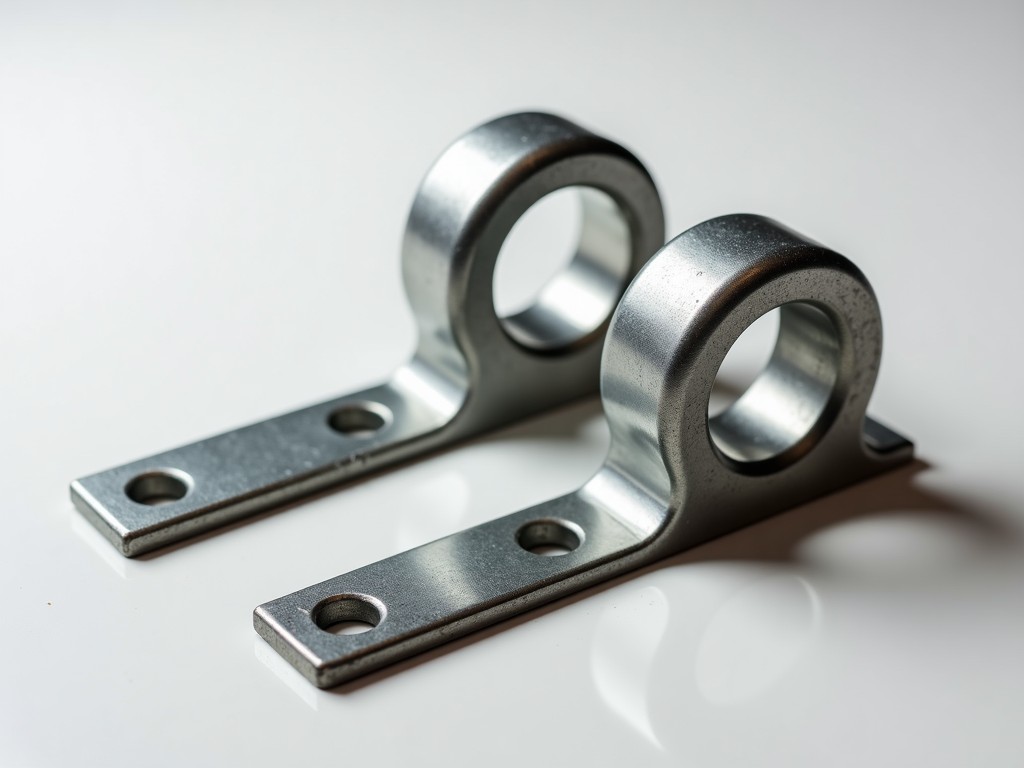
Steel column mason clamps are specialized fastening devices designed to secure formwork, scaffolding, or temporary supports to structural steel columns during construction. They provide a reliable, non-destructive attachment method that avoids welding or drilling into the column flange or web, preserving the integrity of the primary structural element. These clamps are engineered to transfer lateral and vertical loads from formwork or bracing systems directly into the column’s load-bearing capacity through frictional grip and mechanical interference.
Unlike bolted or welded connections, mason clamps rely on high-strength steel jaws that clamp tightly against the column flange when actuated by a threaded spindle or lever mechanism. The contact surfaces are often hardened or treated to resist wear and prevent slipping under cyclic loading. Proper installation ensures the clamp maintains its holding force even under vibration, wind load, or dynamic concrete pour pressures, making them essential for high-rise construction, bridge formwork, and industrial plant erection where column integrity must remain uncompromised.
Material selection is critical: clamps are typically forged from alloy steel grades such as 4140 or 4340, heat-treated to achieve tensile strengths between 800–1000 MPa and yield strengths exceeding 600 MPa. This ensures resistance to permanent deformation under repeated clamping cycles. Surface treatments like zinc plating or phosphate coating are applied to inhibit corrosion in humid or alkaline environments common on construction sites. The design avoids stress concentrations through generous radii and smooth transitions in the jaw geometry.
The clamping force is generated by a trapezoidal-threaded spindle or cam lever system, allowing precise adjustment to match column flange thicknesses typically ranging from 8mm to 25mm. The jaw opening is adjustable via a threaded rod with locknut, enabling rapid setup without tools. A safety pin or secondary lock mechanism prevents accidental loosening due to vibration. The clamp’s effective load capacity depends on the friction coefficient between jaw and flange, the clamp’s preload, and the column’s surface condition — typically rated for safe working loads of 15–25 kN per clamp when installed correctly on clean, dry, mill-scale steel.
Load distribution is optimized through a wide, flat jaw face (typically 40–60mm wide) that spreads pressure over a larger area, minimizing local indentation or damage to the column flange. The jaw angle is designed to self-tighten under load — as downward force increases, the mechanical advantage increases clamping force, providing inherent stability. This self-energizing feature distinguishes mason clamps from simple friction grips and allows them to maintain performance even if initial preload settles slightly over time.
Each clamp includes a visible scale or indicator to confirm proper spindle extension, helping installers avoid over-tightening (which risks flange deformation) or under-tightening (which risks slip). The spindle is often equipped with a tommy bar hole for manual torque application, and some models incorporate a torque-limiting feature to prevent over-clamping. These design elements reduce installer error and improve consistency across large-scale projects where dozens of clamps are used per column.
The primary structural components — jaws, spindle, and body — are manufactured from forged alloy steel to ensure homogeneity and eliminate internal defects common in castings. Forging aligns the grain flow with stress paths, improving fatigue resistance by up to 40% compared to machined bar stock. The spindle is typically made from 4140 steel, hardened to HRC 28–32 for wear resistance while retaining toughness to avoid brittle fracture under impact.
Surface treatments are selected based on environmental exposure. For indoor or short-term outdoor use, zinc electroplating (8–12 µm thickness) provides adequate corrosion resistance. For prolonged exposure to moisture, alkaline concrete wash, or coastal environments, hot-dip galvanizing (55–85 µm) or phosphate-oil coating is preferred. Some models offer optional stainless steel (304 or 316) jaws for use in food processing, pharmaceutical, or wash-down areas where carbon steel contamination must be avoided.
All moving parts — spindle threads, locknuts, and pivot points — are lubricated with molybdenum disulfide-based grease during assembly to prevent galling and ensure consistent torque-to-clamp-force relationship. The lubricant is chosen for its stability under high pressure and resistance to washout by concrete slurry or rain. Periodic re-lubrication is recommended after every 20–30 clamping cycles or after exposure to harsh cleaning agents.
Steel column mason clamps are most commonly used in concrete formwork systems where vertical loads from wall or slab forms must be resisted without penetrating the column. They allow formwork to be tied directly to the column, reducing the need for external bracing or tie-backs to floors or walls — particularly valuable in congested urban sites or when working near existing structures. This direct attachment minimizes deflection and improves formwork alignment, leading to better concrete surface finish and dimensional accuracy.
In steel erection, they secure temporary bracing, guy lines, or safety cables to columns during the erection phase before permanent connections are made. This is critical in high-rise construction where wind loads can induce significant lateral forces on partially assembled frames. The clamps enable rapid installation and removal, allowing crews to reposition bracing as the structure rises without delaying the critical path.
Industrial plant construction uses mason clamps to support piping racks, cable trays, or equipment foundations during installation. For example, when erecting a refinery or power plant, temporary supports for large-bore piping are often clamped to structural columns to maintain alignment during welding and stress-relief operations. The non-destructive nature of the clamp allows these supports to be removed and reused without leaving marks or requiring touch-up painting on the column.
They are also employed in maintenance and retrofit scenarios — such as installing insulation cladding, access platforms, or fall arrest systems on existing columns — where drilling or welding is prohibited due to fire hazards, coating damage, or structural certification constraints. Their reusability and ease of deployment make them a cost-effective solution for temporary access needs across multiple maintenance cycles.
Before installation, the column flange must be cleaned of loose mill scale, rust, concrete residue, or paint using a wire brush or grinder — surfaces should be bare metal to ensure adequate friction. Clamps should not be installed over paint, galvanizing, or epoxy coatings thicker than 150 µm unless the coating is specifically rated for shear transfer. The jaw opening is adjusted to match the flange thickness plus approximately 2mm to allow for proper engagement without binding.
The clamp is placed on the flange with the jaws aligned perpendicular to the column axis. The spindle is turned clockwise using a tommy bar until the indicator shows the correct extension — typically marked on the spindle body. Over-tightening beyond the recommended extension can cause flange yielding or clamp deformation; under-tightening risks slippage. A torque wrench is not typically used due to friction variability, but the visual indicator provides a reliable proxy for preload when used consistently.
After initial tightening, the clamp should be rechecked after the first concrete pour or load application, as settling or creep may reduce preload. A secondary check after 24 hours is recommended for critical applications. Clamps must never be used as a permanent connection — they are strictly for temporary support. Removal should be done by reversing the spindle motion; never strike the clamp with a hammer to loosen it, as this can damage the jaws or spindle threads.
For multiple clamps on a single column, spacing should be uniform and symmetrical to avoid inducing torsion or bending in the column. Clamps should be installed in pairs opposite each other to balance lateral forces. Inspect all clamps before each use for signs of wear, cracking, or deformed jaws — any clamp showing permanent deformation, cracked spindle, or worn threads must be removed from service immediately.
| Feature | Steel Column Mason Clamp | Welded Bracket | Bolted Flange Plate |
|---|---|---|---|
| Installation Time | 1–2 minutes per clamp | 10–15 minutes (welding + cleanup) | 5–8 minutes (drilling + bolting) |
| Impact on Column | None — non-destructive | Permanent heat-affected zone; requires NDT | Holes weaken flange; requires reinforcement if over 20% area |
| Reusability | High — 50+ cycles with inspection | None — permanent | Low — bolts often damaged on removal |
| Load Capacity (Safe Working) | 15–25 kN per clamp | 50–100+ kN (depends on weld) | 20–40 kN (bolt grade 8.8) |
| Skill Required | Minimal — visual indicator guides | Certified welder + fire watch | Basic — drill and torque wrench |
| Environmental Constraints | None — usable in wet, hot, or confined spaces | Fire hazard; fumes; not allowed in explosive zones | Requires dry access; corrosion risk in holes |
| Cost per Use | Low — amortized over many uses | High — labor, consumables, inspection | Medium — bolt replacement labor |
*Values are typical ranges; actual performance depends on installation quality, column condition, and load dynamics. Mason clamps offer optimal balance of speed, safety, and reversibility for temporary structural attachments.
Each clamp undergoes dimensional inspection of jaw flatness, spindle thread pitch, and throat opening using calibrated gauges. The jaw contact surfaces are checked for parallelism within 0.1mm to ensure even load distribution. Hardness testing is performed on critical zones — jaws and spindle threads — to confirm they fall within the specified HRC range, preventing premature wear or deformation under load.
Proof load testing is conducted on a sampling basis: clamps are subjected to 1.5 times their rated working load for 1 minute without permanent deformation or slip. This validates the frictional grip mechanism and clamping force retention. Magnetic particle inspection is used on forged components to detect surface or near-surface cracks that could propagate under cyclic loading. All test results are traceable to batch numbers and retained for quality audits.
Manufacturing tolerances are tightly controlled: spindle lead error must be within ±0.05mm per revolution to ensure consistent torque-to-clamp-force relationship. The jaw opening adjustment range is designed to accommodate ±10% variation in flange thickness without requiring re-machining. Lubrication is applied uniformly during assembly, and excess is wiped to prevent attraction of concrete dust or debris that could interfere with operation.
Packaging is designed to prevent damage during transit: clamps are placed in corrugated dividers or plastic trays to avoid jaw-to-jaw contact, which could cause nicks or galling. Each box includes a QR code linking to the installation manual, material certificate, and test report batch number. This supports traceability and ensures end-users have access to the correct technical documentation for their specific product lot.
While standard mason clamps accommodate flange thicknesses from 8mm to 25mm, custom versions are available for atypical sections. For very thick flanges (e.g., 30–50mm in heavy bridge columns), extended spindles and deeper jaw throats can be fabricated. Conversely, for thin-walled hollow sections or lightweight columns, reduced-profile jaws with wider contact faces minimize local stress while maintaining clamping force.
Special coatings can be applied based on project environment: offshore platforms may require duplex systems (zinc-rich primer + polyurethane topcoat), while cryogenic applications demand low-temperature toughness testing and specific alloy selection (e.g., 9% nickel steel). For cleanroom or semiconductor fabrication facilities, electropolished stainless steel (316L) versions are available to eliminate particulate shedding and facilitate cleaning.
Custom branding or laser etching of project codes, asset numbers, or inspection due dates is possible on the clamp body or spindle. This aids in inventory management and maintenance tracking on large-scale projects where hundreds of clamps are deployed. Some clients request integrated safety features such as a visible red indicator that appears if the clamp is over-tightened beyond safe limits — a feature achievable through calibrated spindle deformation zones.
OEM clients often request modified spindle ends — such as hex sockets for power tool drive, or quick-release pins for faster removal in high-cycle applications. These modifications are developed in consultation with the client’s erectors and safety engineers to ensure compatibility with existing workflows and tooling. All customizations retain the core load-path integrity and are subject to the same quality control protocols as standard models.
For technical inquiries, customization requests, or to request a quotation with load test reports and material certifications, please contact our engineering team.
Request Technical Consultation




