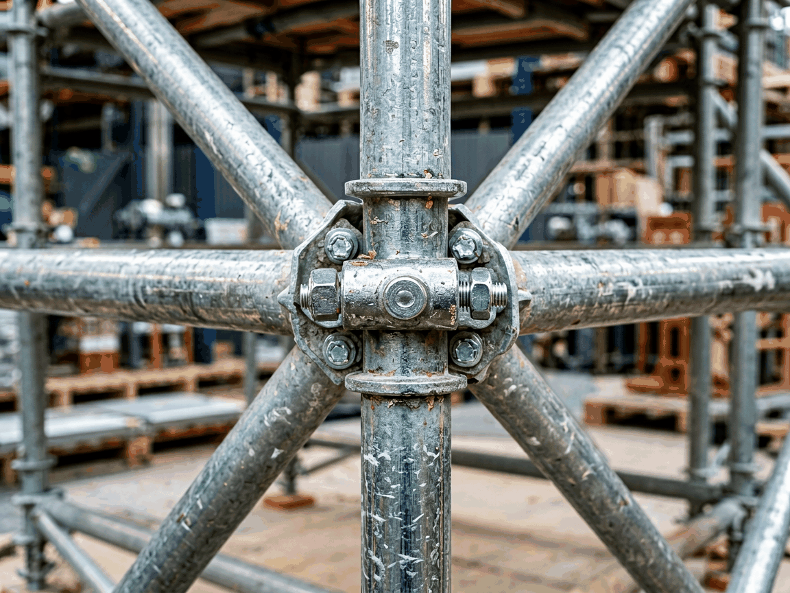
Spigot joint pins are precision-engineered components designed to securely connect scaffold tubes end-to-end, forming continuous vertical or horizontal members. Unlike couplers that clamp externally, spigot pins insert into the internal bore of scaffold tubes, creating a flush, rigid joint that maintains alignment and load path continuity. This connection method is critical in system scaffolding where dimensional accuracy and structural integrity directly impact safety and efficiency.
The pin’s geometry—typically a solid cylindrical shaft with defined chamfers, tolerances, and surface finish—ensures reliable insertion and resistance to radial and axial forces. Material selection, heat treatment, and dimensional control are not optional features but fundamental requirements for performance under cyclic loading and environmental exposure.
Standard spigot joint pins for scaffolding are manufactured to match the internal diameter of common scaffold tube sizes, primarily 48.3 mm OD × 4.0 mm wall (yielding ~40.3 mm ID) and 48.3 mm OD × 3.2 mm wall (~41.9 mm ID). Pin outer diameter is held to tight tolerances—typically ±0.15 mm—to ensure interference fit or controlled slip resistance based on design intent.
Length varies according to tube wall thickness and required overlap, commonly ranging from 100 mm to 150 mm. Chamfers at both ends (usually 1–2 mm at 30°–45°) facilitate insertion and prevent edge damage during handling. Surface roughness (Ra) is maintained below 1.6 μm to reduce friction during assembly and minimize wear over repeated use cycles.
Straightness is controlled to less than 0.5 mm over the full length to prevent binding or misalignment during installation. These dimensional controls are verified using calibrated gauges and coordinate measuring machines (CMM) during production, not assumed.
The most common material for spigot joint pins is carbon steel, specifically grades equivalent to S355JR or ASTM A36, chosen for its balance of tensile strength (typically 340–470 MPa), yield strength (~235 MPa), ductility, and weldability. These properties allow the pin to deform plastically under extreme overload before brittle failure, providing a visible warning sign.
For environments requiring enhanced corrosion resistance—such as coastal, industrial, or long-term outdoor use—pins may be made from galvanized steel (hot-dip zinc coating ≥55 μm) or, less frequently, stainless steel (e.g., A2/AISI 304). Galvanization adds a sacrificial layer that protects the substrate; stainless steel offers inherent resistance but at higher cost and lower strength (~500–700 MPa tensile for austenitic grades).
Heat treatment is generally not applied to standard pins, as the as-rolled or cold-worked condition of the base steel provides sufficient hardness (typically 120–180 HB) for wear resistance without sacrificing toughness. Hardening treatments are avoided unless specifically required for high-abrasion applications, as they can reduce impact toughness.
The primary function of a spigot joint pin is to transfer axial compressive and tensile loads between scaffold tubes while resisting shear and bending moments. In compression, the load is borne by the pin’s cross-sectional area against the tube’s inner wall; in tension, resistance comes from friction and any mechanical interference or shoulder design.
Typical axial load capacity for a properly installed pin in 48.3×4.0 mm tube exceeds 25 kN under static conditions, depending on material and fit. Shear capacity—critical when resisting lateral forces from wind or live loads—is typically 15–20 kN, calculated based on the pin’s cross-sectional area and material shear strength (approx. 0.6 × tensile strength).
Fatigue performance is influenced by surface finish, stress concentrations at chamfer roots, and the presence of corrosion or debris. Pins with smooth transitions and consistent hardness exhibit better fatigue life under cyclic loading. Regular inspection for bending, galling, or corrosion is essential, as even minor damage can reduce load capacity significantly.
| Parameter | Spigot Joint Pin | External Coupler (e.g., Swivel/Fixed) |
|---|---|---|
| Joint Profile | Flush, internal | External, bulky |
| Installation Speed | Moderate (requires alignment) | Fast (clamp-on) |
| Axial Load Capacity | High (continuous tube) | Limited by coupler slip |
| Shear Resistance | Good (pin in shear) | Dependent on bolt torque |
| Dimensional Accuracy | Excellent (maintains tube alignment) | Lower (play in coupler) |
| Reusability | High (if undamaged) | High |
| Corrosion Trap Risk | Low (open ends allow drainage) | Higher (crevices under clamp) |
Note: Values are typical; actual performance depends on tube specifications, installation quality, and environmental conditions.
Each production batch undergoes dimensional verification using go/no-go gauges for outer diameter and length, with statistical process control (SPC) applied to critical dimensions. Straightness is checked using a precision bench and dial indicator, with rejection if deviation exceeds 0.5 mm over 300 mm.
Surface quality is visually inspected for cracks, laps, seams, or excessive roughness. Edges must be free of burrs that could damage tube interiors or impede insertion. Chamfer angles and widths are verified using optical comparators or profile projectors to ensure consistency.
Material traceability is maintained via mill certificates linking each batch to its chemical composition and mechanical properties. For galvanized pins, coating thickness is measured using magnetic induction probes on samples per batch, with adherence to ISO 1461 or ASTM A123 standards. No pin is released without documented conformity to drawing specifications.
Spigot joint pins are predominantly used in tube-and-coupler scaffolding systems where long, continuous standards (verticals) or ledgers (horizontals) are required, such as in high-rise construction, façade access, shoring, and formwork support. Their flush profile eliminates snag hazards and allows close boarding or plank placement without interference.
In system scaffolding (e.g., Ringlock, Cuplock), spigot pins may serve as secondary alignment aids or be integrated into proprietary connectors, though primary coupling is often handled by nodal points. Nevertheless, they remain essential in adapting system tubes to traditional tube-and-coupler needs or extending lengths beyond standard module sizes.
Industries benefiting from this component include commercial construction, petrochemical maintenance, shipbuilding, and event staging—anywhere scaffold integrity, alignment precision, and reusability are non-negotiable. The pin’s simplicity belies its role in enabling safe, efficient, and modular vertical structures.
While standard dimensions cover the majority of scaffold tube sizes, customization is available for non-standard tubes (e.g., 42 mm, 50 mm, or 60 mm OD) or special requirements such as extended length for overlapping joints in temporary bridges or increased diameter for higher load paths. Chamfer geometry can be adjusted to match specific tube end preparations or insertion tools.
Material options extend beyond carbon steel to include pre-galvanized tubes (for pins cut from tube), duplex stainless steel for aggressive environments, or low-temperature steel for arctic conditions. Coatings can be customized—such as zinc-nickel for enhanced corrosion resistance or powder coating for identification—though these add cost and may affect friction characteristics.
Ordering requires clear specification of: tube OD and wall thickness (to determine pin OD and length), material grade, surface finish (self-color, galvanized, etc.), quantity, and any special tolerances. Lead time depends on material availability and complexity; standard pins typically ship within 2–4 weeks, while custom orders may take 6–8 weeks. Samples are available upon request for validation.
For technical inquiries, custom specifications, or quotation requests regarding spigot joint pins for your scaffolding application, please contact our engineering team.
Request Technical Specification or Quote




