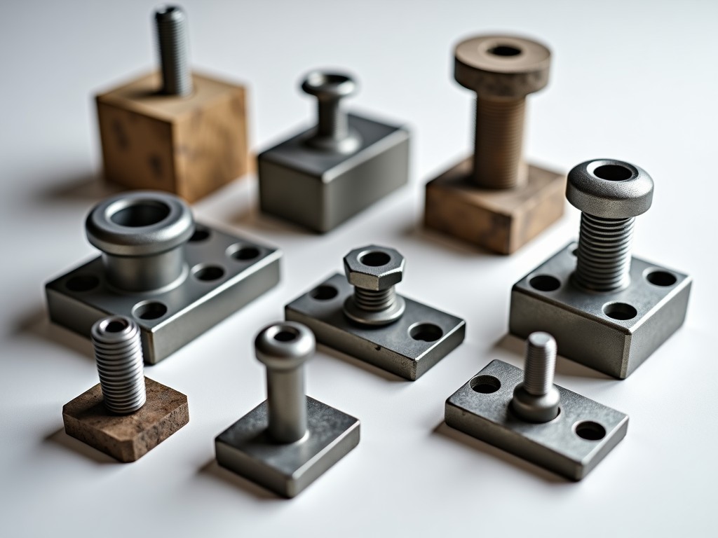
Shoring jacks for slab applications are adjustable steel support systems designed to temporarily bear formwork loads during concrete pouring and curing. They provide vertical load transfer from the slab soffit to the ground or a stable substrate, ensuring structural stability until the concrete achieves sufficient strength to support itself.
These systems are engineered to handle sustained dead loads, live loads from construction activity, and lateral stability requirements as defined in formwork design calculations. Proper selection and installation reduce the risk of formwork failure, slab deflection, or uneven settling during the critical early-age concrete phase.
Shoring jacks are rated by their safe working load (SWL), typically expressed in kilonewtons (kN) or tons, which represents the maximum axial load they can sustain under specified conditions. Common SWL ratings for slab shoring jacks range from 20 kN to 50 kN per jack, depending on tube diameter, wall thickness, and extension length.
The adjustment range is determined by the inner and outer tube lengths, with most models offering 500 mm to 1000 mm of vertical travel via a threaded collar and pin-hole system. This allows precise height matching to varying soffit elevations and slab thicknesses across a single pour.
For example, a jack with a 60 mm outer tube, 3 mm wall thickness, and 750 mm adjustment range may achieve an SWL of 30 kN at full extension, decreasing to 40 kN at mid-height due to improved column stability. Load capacity must always be verified against the formwork design’s point load requirements.
The primary structural components—outer and inner tubes, threaded collars, and base plates—are manufactured from hot-rolled or cold-formed structural steel, commonly grades S235JR or S355JR per EN 10025. These grades provide a balance of yield strength, ductility, and weldability suitable for cyclic loading and reuse.
Tube wall thicknesses typically range from 2.5 mm to 4.0 mm, with thicker sections used in higher-load or long-reuse applications. The threaded collar is often forged from carbon steel and machined to ACME or trapezoidal thread standards to ensure smooth operation under load and resistance to thread galling.
To extend service life in harsh construction environments, jacks are coated via hot-dip galvanizing (minimum 55 µm zinc coating per EN ISO 1461) or powder coating. Galvanizing provides sacrificial protection against moisture and concrete alkalinity, while powder coating offers UV resistance and aesthetic uniformity for rental fleet management.
The base plate distributes the jack’s load onto the supporting surface—whether soil, compacted gravel, or a steel spreader plate—reducing ground pressure to prevent sinking or punching shear. Standard base plates are 150 mm x 150 mm square or 160 mm diameter, made from 6 mm thick steel, welded concentrically to the outer tube.
On the soffit side, the head assembly typically features a U-head or flat top plate with a captive hole to secure timber beams or steel walers. U-heads accommodate 100 mm nominal timber, while flat heads are used with steel soffit systems or plywood formwork. Some designs include a swivel capability (±5°) to accommodate minor slab slope without inducing eccentric loading.
Both base and head plates include pre-drilled holes for anchoring to strongbacks or substrate fixation when required by design, particularly in seismic zones or elevated slabs where lateral restraint is critical.
| Feature | Standard Pipe Jack | Frame-Type Shoring Jack | Tower Jack System |
|---|---|---|---|
| Typical SWL per Unit | 20–40 kN | 30–50 kN | 50–100 kN+ |
| Adjustment Range | 500–1000 mm | 600–1200 mm | 1000–2000 mm (via mast) |
| Reusability Cycles | 50–100 | 100–200 | 200+ |
| Setup Complexity | Low | Medium | High (requires bracing) |
| Best Suited For | Residential slabs, beams | Commercial floors, grids | Industrial slabs, transfer beams |
*Values are typical ranges; actual performance depends on extension length, material grade, and loading conditions. Consult formwork design calculations for point load verification.
Proper installation begins with verifying the substrate’s bearing capacity—soil must be compacted to at least 95% Proctor density or supported by mudsills or steel plates to prevent differential settling. Jacks should be positioned plumb within ±2° deviation to avoid eccentric loading that reduces effective capacity.
Load distribution must align with the formwork layout: jack spacing is determined by the tributary area of the slab and the safe load capacity of the joists or bearers. Overloading a single jack beyond its SWL, even temporarily, risks permanent deformation or buckling.
Before concrete pour, all jacks should be inspected for straight thread engagement, undamaged tubes, and secure head/base connections. Any jack showing bends, cracks, or thread damage must be removed from service. Post-pour, jacks remain in place until the concrete reaches sufficient strength—typically 70% of design strength—as confirmed by cylinder tests or maturity monitoring.
Standard shoring jacks are available in fixed sizes, but custom lengths, increased wall thickness, or special coatings can be manufactured for project-specific demands. For example, ultra-low profile jacks (under 300 mm retracted) are used in basement retrofits, while extended-reach models (up to 3 m) serve elevated transfer slabs.
Optional accessories include screw jacks with hand wheels for rapid adjustment, laser-cut base plates for precise hole patterns, and nut retainers to prevent collar dislodgement during vibration. Surface treatments can be adjusted for marine environments (e.g., epoxy primer + polyurethane topcoat) or high-reuse rental fleets (e.g., color-coded powder coating by size).
Procurement typically involves specifying quantity, SWL requirement, adjustment range, and surface finish. Lead times vary from stock availability (3–5 days) to custom fabrication (4–6 weeks). Volume discounts apply for rental fleet purchases, and many suppliers offer buy-back or trade-in programs for used equipment.
Manufacturing quality control begins with material certification—each steel coil is accompanied by a mill test report (MTR) confirming chemical composition and mechanical properties. Tubes are inspected for straightness, ovality, and wall thickness tolerance before cutting and forming.
Threaded collars undergo go/no-go gauge testing to ensure pitch diameter and flank angle compliance. Welds on base and head plates are visually inspected per EN ISO 5817 and may be subjected to dye penetrant testing for critical applications. Final assembly includes torque verification of locking pins and functional testing of the adjustment mechanism under load.
While individual jack load testing is not standard for every unit due to cost, statistical batch testing is performed—typically 1 in 50 jacks is loaded to 1.5x SWL to verify no plastic deformation or thread failure. Test reports are available upon request for projects requiring traceability, such as infrastructure or nuclear-grade formwork.
For technical specifications, customization requests, or volume pricing on shoring jacks for slab applications, contact our engineering team to discuss your project’s load requirements, geometry, and reuse expectations.
Request a Quote or Technical Consultation




