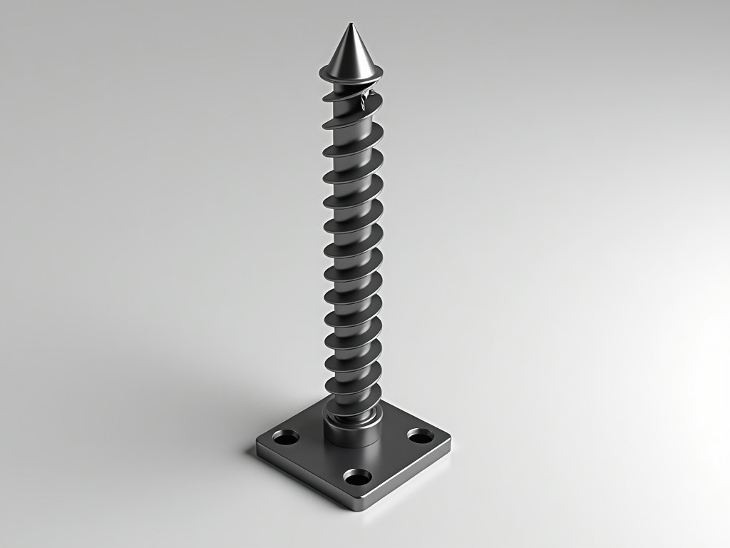
A screw jack post floor support is a height-adjustable vertical load-bearing component designed to transfer structural loads from beams, slabs, or equipment to foundations or subfloors with precise elevation control. It consists of a threaded steel post, a base plate, a top plate or U-head, and a manual or powered adjustment mechanism. These supports are commonly used in temporary shoring, permanent structural adjustments, and industrial equipment leveling where foundation settlement or construction tolerances require compensation. Unlike fixed columns, they allow post-installation height modification without dismantling the supported structure. Industrial applications demand predictable load paths, corrosion resistance, and compatibility with standard formwork or steel framing systems.
Load capacity is determined by post material grade, wall thickness, thread pitch, and end connection design. Standard models typically support axial loads from 20 kN to 200 kN depending on size and configuration, with safety factors applied per relevant standards such as EN 1065 or AS 3610. The adjustment range is defined by the screw length and thread engagement, commonly offering 300 mm to 600 mm of vertical travel. Thread types include ACME or trapezoidal profiles for self-locking behavior under static load, preventing unintended descent. Base and top plates are engineered to distribute load over sufficient area to prevent localized deformation of soft substrates or damage to structural members.
Posts are predominantly manufactured from cold-formed or hot-rolled structural steel, with S355JR and Q345B being common grades due to their yield strength and weldability. For corrosive environments, hot-dip galvanizing per EN ISO 1461 or epoxy coating systems are applied to achieve minimum 55 μm zinc thickness or equivalent barrier protection. Stainless steel variants (AISI 304 or 316) are available for chemical or washdown areas where carbon steel coatings may degrade. Threaded components are often case-hardened or made from alloy steel to resist wear and galling during repeated adjustment cycles. Welding procedures follow qualified specifications to ensure full penetration and ductility at critical joints.
Manual adjustment is typically achieved using a forged steel handle inserted into a socket at the top of the screw, providing mechanical advantage for lifting loads up to rated capacity. For frequent or heavy-duty adjustments, pneumatic or electric drive units can be mounted to the jack post, enabling remote or automated positioning. Accessories include U-heads for securing timber or steel beams, screw jacks with swivel tops to accommodate angled connections, and extension tubes for increased reach. Locking pins or nuts are often incorporated to secure the adjusted position against vibration or shock loads. All moving parts are designed with adequate lubrication points and contamination resistance.
In precast concrete plants, screw jack posts support formwork and falsework during panel casting, allowing fine-tuning of elevation to match design tolerances and accommodate slab camber. They are used beneath conveyor systems and packaging lines to compensate for floor unevenness, ensuring consistent product transfer and reducing wear on belts and rollers. In steel erection, they provide temporary support for primary beams during connection bolting, enabling controlled load transfer as permanent connections are made. Machine tool foundations utilize them to maintain precise alignment under dynamic loads, where even minor settlement could affect machining accuracy. Their adjustability makes them suitable for retrofit projects where existing foundations have settled unevenly.
The required load capacity must include both dead and live loads, with dynamic factors applied for vibrating equipment or moving loads. Deflection limits should be evaluated based on the supported element’s sensitivity—typically L/360 for framing and L/600 for precision equipment. The adjustment range must exceed expected settlement or construction tolerance plus a margin for future maintenance access. Lateral stability is assessed by checking slenderness ratio (Kl/r) against buckling limits, particularly for tall, lightly braced posts. Connection details at top and bottom must transfer load without inducing eccentricity or prying forces. Environmental exposure dictates coating selection and maintenance intervals.
Each unit undergoes dimensional verification of thread pitch, straightness, and plate flatness before assembly. Load testing is performed on a sampling basis using calibrated hydraulic rams to confirm ultimate and working load capacities, with results documented per batch. Coating thickness is measured via magnetic induction or ultrasonic methods to ensure compliance with corrosion protection standards. Thread function is checked for smooth operation and self-locking capability under load. Material certificates are maintained for steel grades and coating batches. Final inspection includes verification of all accessories and correct labeling of safe working load (SWL) and adjustment range.
| Parameter | Typical Range | Notes |
|---|---|---|
| Outer Diameter (Post) | 48 mm – 114 mm | Depends on load capacity and slenderness requirements |
| Wall Thickness | 3 mm – 8 mm | Thicker walls increase buckling resistance and durability |
| Adjustment Range | 300 mm – 600 mm | Longer ranges available with extension tubes |
| Safe Working Load (SWL) | 20 kN – 200 kN | With 3:1 or 4:1 safety factor depending on standard |
| Thread Type | ACME or Trapezoidal | Self-locking under static load; prevents creep |
| Coating (Carbon Steel) | Hot-dip Galvanized (≥55 μm Zn) | Or epoxy/polyester powder coat for specific environments |
Non-standard lengths, top plate configurations (e.g., offset U-heads, beam clamps), and base plate shapes (square, round, or slotted for anchor bolting) are available to suit specific connection geometry. Thread direction can be specified as left-hand or right-hand depending on installation ergonomics or system integration. For OEM equipment manufacturers, jack posts can be supplied with pre-drilled mounting holes, integrated load indicators, or matched to existing adjustment systems. Packaging options include individual wrapping, bundle strapping, or steel stillages for bulk transport to site. All customizations are subject to engineering review to ensure load path integrity and compliance with applicable standards.
For technical inquiries, load capacity calculations, or to request a quotation tailored to your project specifications, please contact our engineering team.
Contact Us for Technical Support




