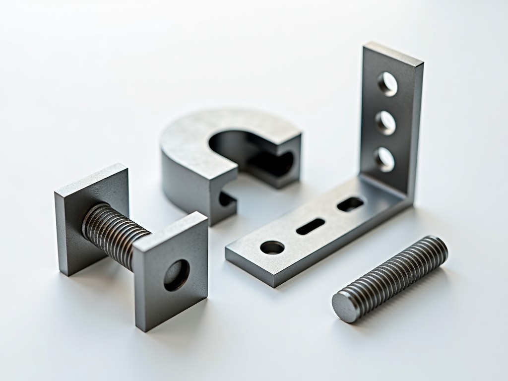
Universal clamps are critical connection components in modular scaffolding systems, enabling secure attachment of horizontal ledgers, transoms, and diagonal braces to vertical standards. Unlike fixed or proprietary connectors, universal clamps provide angular flexibility, allowing installation at various angles to accommodate irregular geometries, retrofit scenarios, or complex facade access requirements. Their design centers on a rotating collar mechanism that grips the scaffold tube via friction and mechanical interlock, maintaining load path integrity under dynamic and static loads.
The primary function of a universal clamp is to transfer axial, shear, and moment forces between scaffold tubes while permitting rotational adjustment. This adaptability reduces the need for custom-fabricated nodes, lowering material waste and on-site labor time. Engineers select universal clamps based on load capacity, tube compatibility, corrosion resistance, and ease of installation under site constraints such as limited access or adverse weather.
| Parameter | Specification |
|---|---|
| Compatible Tube Diameter | 48.3 mm OD (standard scaffold tube) |
| Maximum Safe Working Load (SWL) | 6.2 kN axial, 3.1 kN shear (per EN 74:2015, Type B) |
| Rotational Range | 360° continuous adjustment |
| Clamping Mechanism | Forged steel collar with T-bolt and nut (M12x1.75) |
| Material | Hot-dip galvanized S355JR steel (minimum 60 µm coating) |
| Weight | 1.4 kg per unit |
| Standards Compliance | EN 74:2015, BS 1139 Part 2, ANSI/ASSE A10.8 |
| Operating Temperature Range | -20°C to +60°C |
Load ratings are derived from static tensile and shear testing per EN 74, with safety factors applied to account for dynamic effects, eccentric loading, and long-term creep. The 6.2 kN axial SWL assumes concentric loading through the clamp’s centroid; off-axis loads reduce capacity according to the interaction formula specified in the standard. Users must verify eccentricity limits in project-specific calculations, particularly when connecting diagonal braces or eccentric transoms.
The forged steel collar provides superior grain flow and impact resistance compared to cast alternatives, reducing susceptibility to brittle fracture under low-temperature or impact conditions. The T-bolt design allows torque-controlled installation using a standard spanner, ensuring consistent clamping force without specialized tools. Over-torquing beyond 80 Nm risks thread stripping or tube deformation; under-torquing below 50 Nm may result in slip under load.
S355JR steel is selected for its balance of yield strength (minimum 355 MPa), tensile strength (470–630 MPa), and elongation (>20%), providing ductility to absorb overload events without sudden failure. The hot-dip galvanizing process forms a metallurgical bond between zinc and steel, offering barrier and sacrificial protection. Coating thickness is verified via magnetic induction per EN ISO 1461, with routine sampling to ensure compliance.
In aggressive environments—such as coastal zones, industrial pollutants, or concrete alkali exposure—additional protection may be required. Options include duplex systems (galvanizing plus epoxy topcoat) or stainless steel (Grade 316L) for chloride-rich environments. Material substitution affects weight, cost, and installation torque; stainless steel clamps typically require higher torque due to galling resistance and may need lubricated fasteners.
Galvanized coatings develop a protective patina of zinc carbonate over time, which slows corrosion rates. Regular inspection should focus on areas of mechanical damage, thread wear, or coating depletion at contact points. Re-galvanizing is feasible for intact bases but not recommended if base metal shows pitting or loss of section.
Universal clamps are commonly used in facade retention systems where scaffolds must follow curved or stepped building profiles. They enable the creation of raking shores, birdcage scaffolds over irregular plant equipment, and temporary roof supports where standard node spacing cannot be maintained. In retrofit projects, they allow connection to existing structural elements such as steel beams or concrete columns via adapter plates, avoiding the need for drilling or welding.
Installation requires verifying tube cleanliness and absence of burrs or scale that could interfere with clamping force. The collar should be positioned perpendicular to the tube axis before initial tightening to prevent binding. After placing the ledger or brace, the T-bolt is tightened incrementally while checking for tube slip. Final verification includes confirming no rotational movement under hand torque and checking that the clamp body remains flush against the tube.
In high-wind or seismic zones, secondary restraints such as tie-backs or locking pins may be specified to prevent unintended rotation under cyclic loading. While the clamp resists rotation via friction, prolonged vibration can gradually reduce clamping force; periodic retightening is advised in dynamic environments. Documentation of installation torque and inspection dates supports maintenance planning and regulatory compliance.
Each clamp undergoes dimensional verification of collar bore, bolt thread pitch, and flange thickness during production. Mechanical testing includes proof load testing at 1.5x SWL on a sample basis to validate batch consistency. Non-destructive methods such as magnetic particle inspection are applied to high-stress areas like the bolt collar and T-bolt head to detect surface cracks.
Traceability is maintained via batch numbers laser-etched on the clamp body, linking to raw material certificates, galvanizing records, and test reports. This enables root cause analysis in the event of field performance issues and supports audit requirements under ISO 9001 or regional scaffolding regulations. Suppliers should provide material test certificates (MTC) and EN 10204 3.1 inspection documentation upon request.
Visual inspection criteria include checking for coating uniformity, absence of sharp edges or flash, and proper thread engagement. Functional testing involves assembling a standard bay and applying calibrated loads to verify slip resistance and elastic deformation. Any clamp showing permanent deformation, thread damage, or coating breach exceeding 10% of surface area should be quarantined for re-evaluation.





