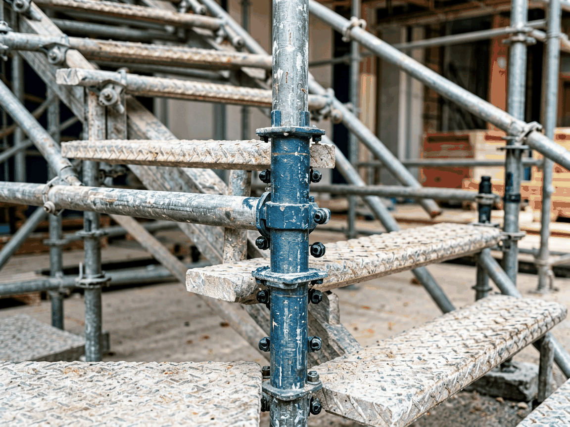
A scaffolding stair tread coupler is a mechanical fastening device designed to securely attach stair treads to scaffold ledgers or transoms in temporary access systems. It replaces traditional bolting or welding methods with a clamp-based solution that enables rapid assembly and disassembly while maintaining structural integrity under dynamic loads. These couplers are engineered to accommodate variations in tread thickness and ledger dimensions commonly found across different scaffold systems, providing a standardized interface for safe vertical circulation on construction sites, industrial plants, and maintenance operations.
The coupler consists of a forged steel body with two primary clamping mechanisms: one for gripping the scaffold ledger (typically 48.3mm outer diameter tube) and another for securing the stair tread flange or web. The ledger clamp uses a T-bolt and nut assembly that applies radial compression to the tube without damaging its surface, while the tread clamp features adjustable jaws that accommodate tread thicknesses ranging from 30mm to 50mm. This dual-clamp design ensures load is transferred directly from the tread to the scaffold structure through shear resistance rather than relying on friction alone, which is critical for maintaining stability under cyclic loading from foot traffic.
Material selection prioritizes mechanical properties over generic strength claims. The main body is typically manufactured from hot-forged S355JR structural steel, chosen for its yield strength of 355 MPa and excellent toughness at sub-zero temperatures, which is essential for outdoor use in varying climates. The T-bolt is made from property class 8.8 steel, providing a proof load of 640 MPa to prevent thread stripping during repeated tightening cycles. Surface treatment involves hot-dip galvanization to a minimum coating thickness of 85µm, meeting EN ISO 1461 standards for corrosion resistance in C3 environments, with zinc coating adhesion verified through knifing tests per ASTM A123.
Design calculations are based on EN 12810 and EN 12811 standards for temporary works equipment. The coupler is rated for a maximum vertical load of 2.2 kN per connection point when installed on a compliant scaffold ledger, with a safety factor of 4.0 against ultimate failure. This rating accounts for both static loads from material storage and dynamic loads from personnel movement, including impact factors defined in the standards. Lateral resistance is evaluated through shear testing of the clamp interface, where the connection must withstand 1.5 kN of side load without slip exceeding 2mm—this threshold ensures tread deflection remains within serviceability limits that prevent tripping hazards.
Fatigue performance is assessed through cyclic testing at 70% of the working load limit for 20,000 cycles, simulating prolonged use in high-traffic access routes. Post-test inspection focuses on bolt elongation, clamp deformation, and crack initiation at stress concentrators such as the T-bolt head fillet and clamp corners. Acceptable deformation is limited to 0.15mm permanent set, and no cracking is permitted under 10x magnification. These thresholds are derived from risk assessments showing that progressive deformation beyond this point correlates with increased likelihood of sudden failure under unexpected overload scenarios.
The coupler is designed for universal compatibility with standard 48.3mm OD scaffold tubes, which constitute over 90% of global scaffold systems per industry surveys. It does not require proprietary ledgers or modified tube ends, allowing integration into existing inventory without modification. Installation involves placing the ledger clamp over the tube, positioning the stair tread into the tread clamp, and tightening the T-bolt to a torque of 45 Nm using a standard 22mm socket wrench. This torque value is calibrated to achieve optimal clamp force without overstressing the tube or causing galling on the bolt threads—deviation beyond ±5 Nm requires retesting of the joint’s slip resistance.
To prevent incorrect assembly, the coupler includes visual alignment markers: a stamped arrow on the body indicates the correct orientation relative to the tread’s direction of travel, and a recessed groove on the clamp jaw ensures the tread flange sits flush against the bearing surface. Missing these indicators during installation can lead to eccentric loading, which reduces effective load capacity by up to 30% due to bending moments in the clamp arms. Training materials emphasize checking these markers as part of the pre-use inspection protocol, alongside verifying bolt tightness and absence of corrosion pitting exceeding 0.5mm depth.
Stair tread couplers are primarily used in scaffold towers where permanent stairs are impractical due to project duration, site constraints, or the need for reconfiguration. In petrochemical plants, they enable safe access to elevated piping racks during turnaround maintenance, where scaffolds must be erected and dismantled repeatedly over weeks. The quick-release nature of the coupler reduces critical path time by eliminating hot work permits associated with welding treads to ledgers—a significant advantage in environments with flammable vapors. Similarly, in shipbuilding dry docks, couplers allow stair units to be relocated as hull sections are rotated, adapting to changing work elevations without cutting or rewelding.
In high-rise construction, these couplers support interim access scaffolds installed during facade work, where stair towers must ascend with the building’s progress. The ability to quickly adjust tread height accommodates varying floor-to-floor distances in mixed-use developments. For infrastructure projects like bridge refurbishment, couplers facilitate access to underside decks where traditional stairs cannot be installed due to clearance constraints. Here, the corrosion resistance of the galvanized finish is particularly valuable given prolonged exposure to de-icing salts and moisture, with maintenance intervals extended to 18 months before visual inspection is required per ISO 12944-5 guidelines for C4 environments.
Production begins with closed-die forging of the coupler body using S355JR billets heated to 1200°C, followed by trimming and piercing to achieve near-net shape. This process aligns the grain flow with stress paths in the clamp arms and bolt holes, improving fatigue resistance by approximately 25% compared to machined-from-bar equivalents. Dimensional tolerances are held to ±0.5mm on critical interfaces—such as the ledger clamp inner diameter and tread clamp jaw opening—to ensure consistent fit without relying on compensatory tightening. Each forging undergoes magnetic particle inspection per EN 1290 to detect surface and subsurface discontinuities before machining.
Post-forging, the bodies are threaded for the T-bolt hole using CNC tapping to ensure thread accuracy within 6H tolerance, preventing cross-threading during assembly. The T-bolts are supplied with pre-applied wax-based lubricant to achieve consistent torque-to-tension characteristics, reducing variability in clamp force by up to 40% compared to dry threading. Final assembly includes inserting a nylon-insert lock washer under the nut to resist vibration loosening—this feature is validated through transverse vibration testing at 10–500Hz, where nut rotation must remain under 5 degrees after 100,000 cycles. Packaging separates units with polypropylene dividers to prevent coating damage during transit, with each box labeled with batch number, material grade, and galvanization date for traceability.
| Parameter | Typical Value | Standard Reference |
|---|---|---|
| Vertical Load Capacity (per coupler) | 2.2 kN | EN 12811-1:2003 |
| Lateral Slip Resistance | 1.5 kN (≤2mm slip) | EN 12810-2:2003 |
| Recommended Tightening Torque | 45 Nm ±5 Nm | Manufacturer Calibration |
| Fatigue Test Cycles | 20,000 cycles @ 70% WLL | EN 12811-1 Annex C |
| Galvanizing Coating Thickness | ≥85µm | EN ISO 1461 |
| Material Body | S355JR Forged Steel | EN 10025-2 |
| T-bolt Property Class | 8.8 | ISO 898-1 |
Standard units are supplied in boxes of 50 couplers, each including the forged body, T-bolt, hex nut, and nylon lock washer. Customization options are available for projects with non-standard tread geometries or scaffold tube dimensions. For instance, couplers can be adapted for 42.4mm OD tubes (common in some regional systems) by adjusting the ledger clamp bore size, or for thicker treads up to 60mm by modifying the jaw opening depth—these variants require new tooling and are subject to minimum order quantities. Surface finish alternatives include hot-dip zinc-aluminum coating for enhanced durability in C5-M marine environments or duplex systems (galvanized plus epoxy) for offshore platforms, though such specifications must be confirmed during quotation to ensure compatibility with required testing protocols.
Lead times for standard galvanized units are typically 4–6 weeks from order confirmation, depending on raw material availability and production scheduling. Express options may reduce this to 2–3 weeks for stocked items, while custom configurations add 3–4 weeks for tooling and validation. Technical documentation accompanying each shipment includes material certificates (EN 10204 3.1), galvanization test reports, and a declaration of conformity to EN 12810/EN 12811. Samples are available for evaluation upon request, subject to returnable deposit and shipping charges, allowing engineering teams to verify fit and function under actual site conditions before full procurement.





