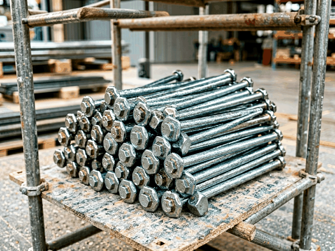
Scaffolding stacking pins are mechanical fasteners designed to vertically align and secure modular scaffold frames during assembly. They transfer compressive loads between stacked frames while resisting lateral displacement caused by wind, worker movement, or material handling. Unlike bolted connections, stacking pins rely on precise dimensional tolerances and material hardness to maintain joint integrity under cyclic loading. Their primary function is to enable rapid, repeatable frame stacking without compromising structural stability in temporary or semi-permanent access systems.
Effective stacking pin performance depends on three interrelated factors: pin diameter, engagement length, and material yield strength. Standard diameters range from 16mm to 22mm to match common scaffold tube tolerances, with engagement lengths typically 40mm to 60mm to ensure sufficient shear area. The pin must deform elastically under overload to prevent sudden failure while maintaining dimensional stability after repeated use. Surface hardness between 35-45 HRC resists abrasion from frame movement without galling, preserving alignment accuracy over hundreds of assembly cycles.
Carbon steel grades such as C45 or 1045 are commonly used for scaffolding stacking pins due to their balance of hardenability, toughness, and cost-effectiveness. These alloys respond predictably to quenching and tempering, allowing manufacturers to achieve consistent core strength (typically 500-700 MPa tensile) with controlled surface hardness. Stainless steel variants (e.g., 304 or 316) are specified for corrosive environments like coastal construction or chemical plants, though their lower hardenability requires larger diameters to match carbon steel performance. Material traceability is maintained through mill test reports to verify composition and heat treatment compliance.
| Parameter | Typical Range | Notes |
|---|---|---|
| Pin Diameter | 16mm, 18mm, 20mm, 22mm | Matches scaffold tube ID tolerances |
| Engagement Length | 40mm–60mm | Determines shear capacity |
| Head Diameter | 24mm–30mm | Prevents pull-through under uplift |
| Material | C45, 1045, 304 SS, 316 SS | Selected per environment |
| Surface Hardness | 35–45 HRC | Measured at pin surface |
Vertical loads are transmitted through direct bearing between the pin head and the upper scaffold frame’s receiver plate, with shear resistance developed along the pin’s engaged length within the lower frame’s tube. The connection resists overturning moments by creating a frictional lock between frame interfaces, supplemented by the pin’s resistance to bending. Finite analysis shows that stress concentrations occur at the pin head fillet and tube entry point, necessitating smooth transitions and controlled radii to avoid crack initiation under fatigue loads. Proper alignment during installation is critical—misalignment exceeding 2 degrees can reduce effective shear area by up to 30%.
Dimensional verification occurs at three stages: raw material inspection, post-machining, and final assembly. Pin diameter and length are checked using calibrated gauges traceable to national standards, with tolerances typically held to ±0.1mm for functional dimensions. Hardness testing follows Rockwell C procedures on cross-sections to confirm case depth and uniformity. Visual inspection identifies surface defects such as laps, cracks, or tool marks that could act as stress concentrators. Batch testing includes tensile sampling to validate mechanical properties before release, with records retained for traceability.
In high-rise facade scaffolding, stacking pins must accommodate dynamic loads from wind-induced oscillation and concrete pump vibration, requiring enhanced fatigue resistance through shot peening or controlled surface rolling. For suspended access systems, pins are often modified with locking collars or weld-on tabs to prevent accidental disengagement during lateral movement. In shoring applications where axial loads exceed 20 kN per leg, pins may be oversized or used in dual-pin configurations to distribute stress. Environmental factors such as temperature extremes or abrasive particulates influence material choice and surface treatments like galvanizing or powder coating to extend service life.
Manufacturers adjust stacking pin designs based on project-specific scaffold system interfaces, load requirements, and site conditions. Common modifications include varying head geometry to match proprietary receiver plates, adding cross-drilled holes for safety cotter pins, or incorporating internal threads for adjustable base collars. Length adjustments accommodate non-standard frame spacing, while material changes address corrosion or temperature extremes. Tooling flexibility allows for batch production of custom variants without prohibitive setup costs, particularly when ordered in quantities exceeding 500 units.
Stacking pins are typically packaged in moisture-resistant cartons with internal dividers to prevent abrasion during transit. Unit counts range from 50 to 200 pieces per box depending on size and weight, with total package weight kept under 25 kg for manual handling compliance. Each box includes a packing list referencing material grade, batch number, and quantity. For export shipments, pins may be treated with volatile corrosion inhibitors (VCI) and sealed in barrier bags to mitigate humidity exposure. Palletized loads use stretch wrapping and corner protectors to stabilize units during forklift handling.
When requesting quotations, specify the scaffold system brand and model to ensure pin compatibility with existing receiver tubes and head plates. Provide required quantity, preferred material (carbon or stainless steel), and any surface treatment needs such as galvanizing or black oxide. Indicate whether pins require secondary features like locking holes or threaded ends. Lead times typically range from 2 to 4 weeks for standard configurations, with custom orders adding 1–2 weeks for tooling validation. Request material certification and inspection reports to confirm compliance with project specifications before acceptance.
For technical inquiries, custom design support, or to request a quote for scaffolding stacking pins, contact our engineering team. Provide your scaffold system details, load requirements, and environmental conditions to receive a tailored solution. We supply detailed dimensional drawings, material test reports, and installation guidance to ensure proper integration into your access or shoring system.
Contact Us for Technical Support




