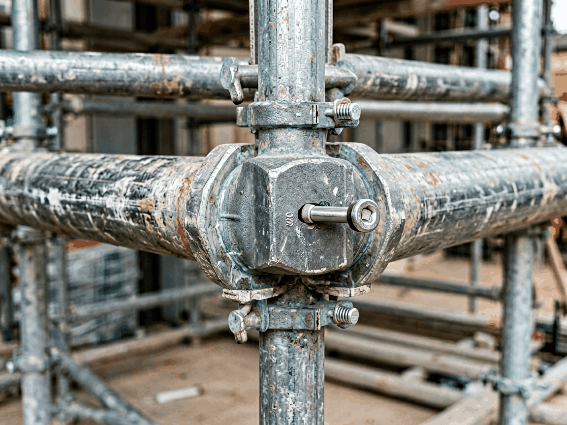
A scaffolding pipe joint spigot pin is a precision-engineered mechanical fastener designed to connect tubular scaffolding members end-to-end by inserting into aligned spigot sockets. It provides axial alignment and shear resistance while allowing for rapid assembly and disassembly. Unlike welded or bolted joints, spigot pins rely on interference fit and mechanical confinement within the socket to transfer loads.
The spigot pin operates by occupying the annular space between the male spigot of one pipe and the female socket of another. When installed, it resists radial movement through contact pressure against the inner socket wall and outer spigot surface. Axial loads are transmitted via bearing stress on the pin ends, while lateral forces induce shear stresses across the pin cross-section. Proper engagement depth ensures that bending moments are minimized at the joint interface.
Design considerations include pin diameter relative to socket tolerance, material yield strength, and surface hardness to resist wear during cyclic loading. Overly loose fits reduce shear capacity; excessive interference can deform thin-walled sockets during installation. Engineers typically specify pin dimensions based on API 5CT or EN 10210 pipe tolerances and expected service loads.
Common materials for scaffolding spigot pins include cold-drawn carbon steel (e.g., C1018, C1045) and alloy steel variants (e.g., 4140) depending on required strength and environmental exposure. Surface treatments such as zinc plating or black oxide are applied to mitigate corrosion in humid or coastal environments. Hardness is typically maintained between HRC 20–30 to balance wear resistance with toughness.
For high-cycle applications, pins may be case-hardened to achieve surface hardness >HRC 50 while preserving a ductile core. Material traceability is maintained through mill test reports (MTRs) for critical projects. Alternative materials like stainless steel (304/316) are available upon request for environments with chloride exposure or stringent hygiene requirements.
Spigot pins are manufactured to match specific scaffolding system tolerances, with common outer diameters ranging from 12mm to 25mm and lengths from 60mm to 150mm. The pin’s chamfered ends facilitate insertion, while retaining features such as cotter pin holes or spring clips prevent disengagement under vibration. Compatibility depends on matching the spigot outer diameter, socket inner diameter, and engagement length.
Manufacturers reference dimensional standards like BS 1139, EN 74, or ANSI/ASSE A10.8 to ensure interchangeability within certified systems. Custom lengths or non-standard diameters are produced based on client-supplied pipe specifications or field measurements. Interference fit is typically targeted at 0.05–0.15mm diameter difference unless otherwise specified by the system designer.
Each batch undergoes dimensional verification using calibrated gauges to confirm pin diameter, length, and chamfer angles. Surface integrity is inspected for cracks, laps, or tool marks under 10x magnification. Hardness testing follows ASTM E18 via Rockwell B or C scale depending on material thickness. Straightness is checked by rolling pins on a surface plate; deviation is limited to 0.1mm per 100mm length.
For plated parts, coating thickness is measured via X-ray fluorescence or magnetic induction to ensure compliance with ASTM B633 (Zn) or equivalent. Mechanical properties are validated through tensile and yield strength tests on sample lots. All inspection records are retained for a minimum of three years and made available upon request.
Scaffolding spigot pins are primarily used in modular frame systems where rapid erection and dismantling are critical, such as facade access, shoring, and formwork support. Their use reduces reliance on skilled labor for bolt tightening or welding, accelerating project timelines. In falsework applications, they enable precise vertical alignment of load-bearing towers under concrete pours.
Beyond temporary works, spigot pins are employed in permanent structures requiring disassembly for maintenance, such as offshore platform access ladders or industrial catwalks. They are also utilized in exhibition stands, stage rigging, and event infrastructure where reusability and tool-free assembly are essential. The joint’s ability to resist rotational slip makes it suitable for diagonal bracing connections when combined with locking collars.
| Joint Type | Assembly Time | Tool Requirement | Reusability | Load Adjustability |
|---|---|---|---|---|
| Spigot Pin | Low (seconds) | None (hand insertion) | High | Fixed alignment |
| Bolted Flange | Medium (minutes) | Wrench/socket | High | Axial adjustment possible |
| Welded Sleeve | High (requires setup) | Welding equipment | None | Permanent |
| Clamp Coupler | Medium | Wrench | High | Limited slip |
The table above compares spigot pins with other common scaffolding joint methods across key operational factors. Spigot pins excel in speed and tool-free installation but offer less axial adjustment than bolted systems. Welded joints provide permanent continuity at the cost of reusability and field repairability. Clamp couplers allow angular flexibility but introduce protruding hardware that may obstruct workspaces.
Standard spigot pins are available in carbon steel with zinc plating, but dimensions, material grade, surface finish, and retaining features can be customized according to project-specific scaffolding system drawings. Clients typically provide pipe outer diameter, socket inner diameter, engagement length, and required load capacity for engineering review.
Minimum order quantities vary based on material availability and complexity of custom features. Prototypes or samples can be machined from bar stock for validation prior to full production. Lead times range from 2–4 weeks for standard items and 6–8 weeks for customized orders involving heat treatment or special plating.
To request a quotation or technical datasheet, provide the following: nominal pipe size, spigot/socket dimensions, material preference (e.g., galvanized, stainless), quantity, and delivery destination. Engineering support is available to confirm compatibility with existing scaffolding inventories or to recommend pin specifications based on calculated shear and bearing stresses.





