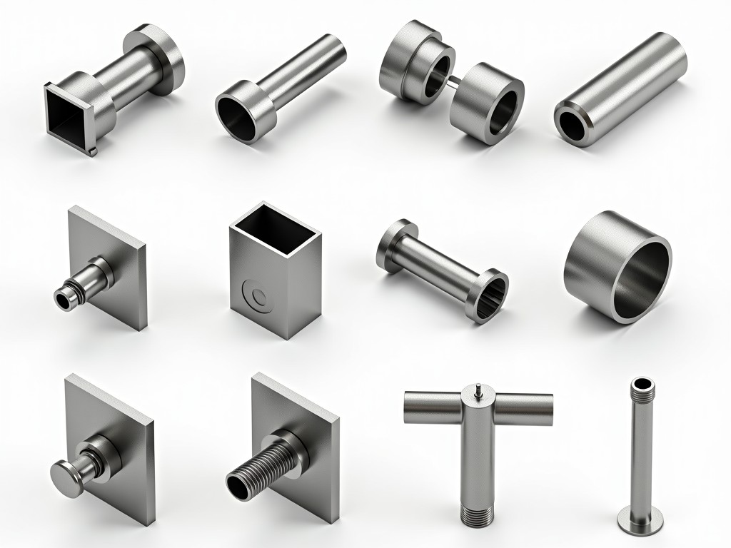
Understanding the names and functions of scaffolding components is essential for safe assembly, compliance with regulations, and efficient procurement. This guide provides visual and technical references for standard parts used in tube-and-coupler, frame, and system scaffolding, enabling engineers and supervisors to identify components correctly and specify replacements with confidence.
Tube-and-coupler scaffolding relies on steel tubes connected by mechanical couplers. The system’s flexibility allows adaptation to complex geometries, but correct identification of each part ensures structural integrity and load distribution as designed.
| Part Name | Function | Typical Dimensions |
|---|---|---|
| Steel Tube | Primary load-bearing member; connects vertically and horizontally | 48.3mm OD × 3.2mm wall; lengths 0.5m to 6.0m |
| Right-Angle Coupler | Connects two tubes at 90°; used for ledgers, transoms, and bracing | Fits 48.3mm tube; forged steel; SWL 6.25kN per BS 1139 |
| Swivel Coupler | Connects tubes at variable angles; essential for facade following and stair towers | Adjustable 0°–360°; same tube compatibility as right-angle |
| Putlog Coupler | Secures putlogs (horizontal bearers) to ledger tubes; allows easy removal | Fits 48.3mm tube; designed for 50mm×50mm timber or steel putlogs |
| Sleeve Coupler | Joins two tubes end-to-end to extend length; maintains axial alignment | Fits 48.3mm tube; internal stop prevents over-insertion |
Frame scaffolding uses prefabricated welded frames connected by cross braces and locking pins. Its modular nature speeds up erection for repetitive structures like façades and slab edges, but mixing parts from different manufacturers can compromise safety due to dimensional tolerances.
System scaffolding (e.g., ring-lock, cup-lock, kwikstage) uses fixed connection points at standardized intervals, enabling rapid assembly with fewer loose parts. While proprietary, most systems share common functional elements whose recognition aids in maintenance and spare part planning.
| Component | Connection Method | Primary Use |
|---|---|---|
| Standard (Vertical) | Prefab rosette or cup at 0.5m or 0.6m intervals | Vertical load transfer; defines bay height |
| Ledger (Horizontal) | End fittings lock into rosettes/cups | Horizontal support; defines bay length |
| Diagonal Brace | Hook or wedge ends | Prevents sway; transfers wind loads |
| Bracket (Putlog) | Wedge or pin connection | Supports working platform at facade |
| Steel Plank/Deck | Hooks over ledgers; may include wind locks | Provides working surface; slip-resistant surface |
Misidentifying scaffolding parts can lead to incorrect assembly, overloading, or failure. Always verify component markings (e.g., manufacturer ID, size, standard compliance) before use. Replace any part with illegible labels, deformation, or corrosion exceeding 10% of cross-section. Maintain a segregated quarantine area for damaged items and document inspections per local regulations (e.g., OSHA 1926.451, EN 12810/12811).
For procurement, specify parts by function, material grade (e.g., S355JO for tubes), finish (hot-dip galvanized per EN ISO 1461), and applicable standard. Avoid generic descriptions like “scaffolding tube” without diameter and wall thickness. When sourcing replacements, match the original system’s connection geometry—interchangeability between brands is not guaranteed even if tube sizes match.
Technical clarity reduces risk. Use this reference to train crews, audit inventory, and communicate requirements to suppliers. Accurate naming prevents delays and ensures that every component on site performs as engineered.
For detailed specifications, custom configurations, or quotation requests regarding scaffolding components, contact our technical team.
Request Technical Specification




