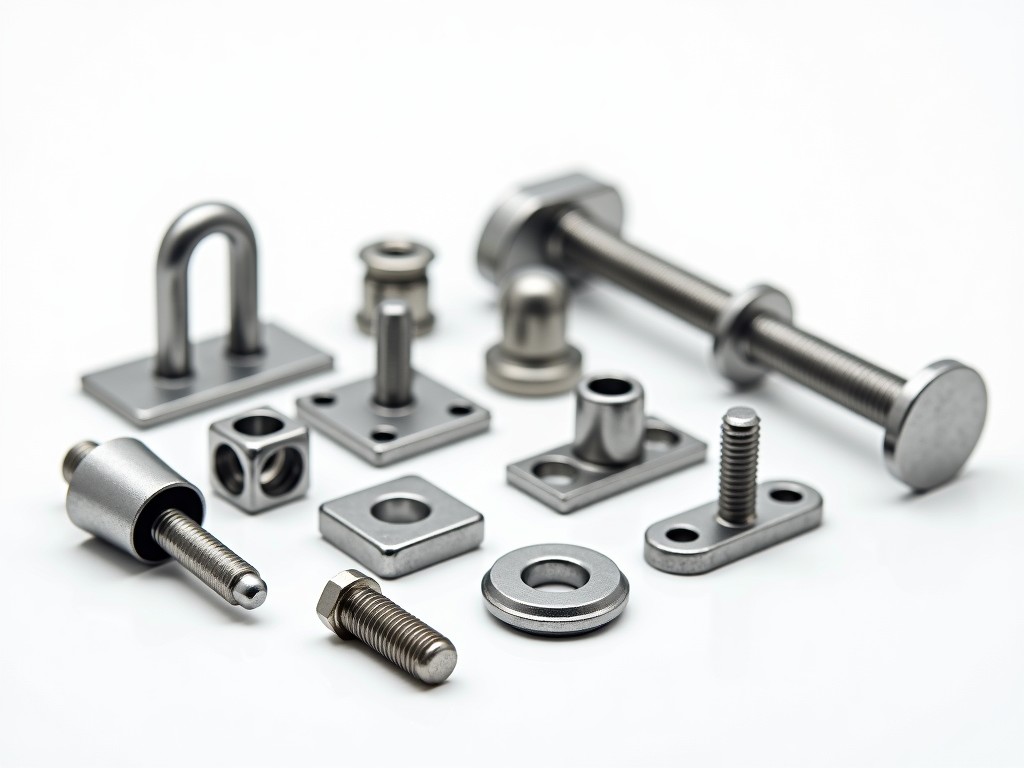
Scaffolding systems rely on a network of interconnected components, each designed to perform specific mechanical and safety functions under load. Understanding the individual roles of these parts is essential for selecting compatible accessories, ensuring structural integrity, and maintaining compliance with temporary works standards such as BS EN 12810-1 and OSHA 1926 Subpart L.
This page explains the core functions of common scaffolding parts and accessories, focusing on their load paths, connection mechanisms, and application-specific purposes. Information is presented to support engineers, procurement specialists, and site supervisors in evaluating component suitability for various construction, maintenance, and industrial access scenarios.
Each component is analyzed based on its primary mechanical function—whether it transfers vertical loads, resists lateral movement, provides lateral bracing, or enables safe personnel access—rather than relying on generic claims of quality or durability.
Vertical load transfer in scaffolding is primarily managed through standards (uprights), which carry the weight of the structure, workers, materials, and environmental loads down to the base or sole plate. The efficiency of this transfer depends on the continuity of the load path, which is maintained through reliable connections between standard sections.
Pins and couplers are the critical interfaces that join standards, ledgers, and transoms. Rigid couplers (such as right-angle or swivel types) must resist slip and rotation under design loads, typically verified through testing to EN 74 standards. The frictional resistance of a coupler is influenced by bolt torque, surface condition, and tube diameter tolerance—factors that directly affect safety factors in design calculations.
Spigots and socket joints, used for connecting standard sections in compression, rely on precise dimensional tolerances to minimize bending stresses at the joint. Misalignment or wear in these components can create stress concentrations, reducing the effective buckling resistance of the standard.
Ledgers run horizontally along the length of the scaffold, connecting standards and providing lateral support to the vertical members. They also serve as attachment points for working platforms and guardrails. The spacing of ledgers affects the effective length of standards in buckling calculations—closer spacing reduces the unsupported length and increases critical load capacity.
Transoms are shorter horizontal members positioned perpendicular to the ledgers, typically supporting the scaffold planks or decking. Their primary function is to transfer distributed loads from the platform to the ledgers and prevent lateral displacement of the standards. Transom spacing must align with plank specifications to avoid excessive deflection or localized overloading.
Diagonal braces, whether facade or plane braces, are essential for resisting racking and torsional forces caused by wind, eccentric loading, or uneven settlement. These members convert lateral forces into tensile and compressive stresses within the brace itself, stabilizing the overall frame. Proper installation angle (typically between 30° and 60° to the horizontal) maximizes their effectiveness in resisting sidesway.
Safe vertical access is facilitated by ladders integrated into the scaffold structure or attached externally. These must provide continuous handholds, slip-resistant treads, and clearances that comply with access width and rung spacing requirements (e.g., 300mm minimum width, 300mm rung spacing). Ladders should extend at least 1m above the landing platform to allow safe transition.
Self-closing gates at access points prevent accidental falls by ensuring openings are not left unattended. These gates rely on spring mechanisms or gravity latches that must remain functional after repeated use and exposure to debris or corrosion. Regular inspection of pivot points and latch engagement is necessary to maintain reliability.
Toeboards, typically 150mm high, are installed along the open sides and ends of working platforms to prevent tools, materials, or debris from falling to lower levels. Their effectiveness depends on secure attachment to the ledger or transom and minimal gap between the toeboard base and the platform surface—gaps exceeding 25mm can compromise containment.
The interface between the scaffold and the ground is managed by base components that distribute loads, accommodate uneven surfaces, and allow for height adjustment. Sole plates (or base plates) spread the reaction force from the standard over a larger area to prevent soil settlement or damage to underlying surfaces such as flooring or pavement.
Adjustable base jacks incorporate a threaded spindle within a hollow housing, enabling fine-tuned vertical adjustment—typically up to 300mm—to compensate for slope or irregular subgrades. The load capacity of a base jack depends on the spindle material, thread engagement length, and resistance to buckling under compression; over-extension beyond the marked limit significantly reduces safety factors.
In applications requiring lateral restraint at the base, such as tied scaffolds or those subjected to significant horizontal forces, base collars or angled brackets may be used to connect the jack to ground anchors or structural elements. These connections must be designed to resist slip and rotation under service loads.
The mechanical properties of scaffolding components are directly influenced by the base material and surface finish. Hot-dip galvanized steel is commonly used for its corrosion resistance in outdoor environments, with a typical zinc coating thickness of 55μm providing protection for 5–15 years depending on atmospheric conditions. The galvanizing process also affects surface roughness, which influences the frictional performance of couplers.
For applications requiring reduced weight or non-magnetic properties (e.g., near MRI facilities or sensitive electronics), aluminum scaffolding systems are used. Aluminum has approximately one-third the density of steel but lower modulus of elasticity, requiring larger cross-sections to achieve equivalent stiffness. Surface treatments such as anodizing improve wear resistance and dielectric properties.
In high-corrosion environments such as marine or chemical processing facilities, stainless steel (e.g., grade 304 or 316) may be selected despite higher cost. The passive chromium oxide layer provides resistance to chlorides and acids, though performance depends on proper passivation after fabrication and avoidance of carbon steel contamination.
Scaffolding parts are not universally interchangeable across systems due to variations in tube diameter, coupling mechanism, and pin spacing. Common tube sizes include 48.3mm OD (standard in many European and Asian systems) and 50.8mm OD (prevalent in North American and some Commonwealth systems). Mixing components with mismatched diameters can result in loose couplers, reduced slip resistance, and compromised structural integrity.
Coupler design also varies—some systems use pressed steel forgings, others use investment-cast or drop-forged components. The method of manufacture affects grain structure, tensile strength, and fatigue resistance. Even within the same nominal specification, differences in manufacturing tolerances can influence assembly ease and long-term reliability.
When integrating accessories such as debris nets, hoists, or weather protection, it is essential to verify that attachment points do not create stress concentrations or interfere with the primary load path. Additional loads from such accessories must be accounted for in the overall scaffold design, including wind uplift and dynamic effects.
| Component Type | Primary Function | Key Design Consideration | Typical Material |
|---|---|---|---|
| Standard (Upright) | Transfers vertical loads to foundation | Buckling resistance; joint alignment | Hot-dip galvanized steel |
| Right-Angle Coupler | Connects ledger/transom to standard at 90° | Slip resistance; bolt torque retention | Forged steel, galvanized |
| Ledger | Horizontal longitudinal support | Span length; connection stiffness | Hot-dip galvanized steel |
| Transom | Supports planks; ties ledgers together | Plank spacing; deflection limit | Hot-dip galvanized steel |
| Diagonal Brace | Resists racking and torsional forces | Installation angle; end fixation | Hot-dip galvanized steel |
| Base Jack | Height adjustment; load distribution | Spindle engagement length; ground bearing | Steel spindle, malleable iron housing |
| Toeboard | Prevents falling objects | Height; gap to platform; secure fixing | Steel or aluminum; wood (non-structural) |
| Ladder (Access) | Provides safe vertical access | Rung spacing; side extension; anti-slip | Steel or aluminum; reinforced polymers |
Environmental and usage conditions significantly influence component selection and maintenance schedules. In high-humidity or coastal environments, even galvanized steel may require additional protective coatings or more frequent inspection for signs of white rust or coating breakdown. Regular cleaning to remove chlorides, sulfates, or industrial pollutants can extend service life.
Components subjected to cyclic loading—such as those in façade access systems or suspended scaffolds—should be evaluated for fatigue resistance. Welded joints, coupler threads, and spindle bases are common fatigue initiation points. Non-destructive testing methods such as magnetic particle inspection or dye penetrant testing may be employed during periodic thorough examinations.
Documentation of component traceability—including material certificates, batch numbers, and inspection records—supports auditability and facilitates recall procedures if a defect is identified. This is particularly important in regulated industries such as offshore oil and gas, nuclear, or pharmaceutical manufacturing.
For technical inquiries regarding component compatibility, load capacity verification, or custom fabrication to project-specific requirements, contact our engineering team.
Request Technical Consultation




