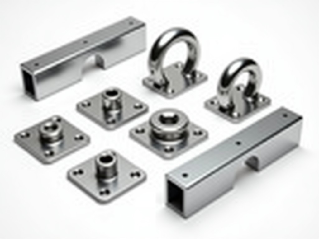
Scaffolding coupler system parts form the critical mechanical interface between scaffold tubes, ensuring structural integrity, load transfer, and safety in temporary works. These components—including right-angle couplers, swivel couplers, sleeve couplers, and putlog couplers—are engineered to clamp, connect, or join steel or aluminum tubes under dynamic loads, wind forces, and worker-induced vibrations. Their performance depends on precise tolerances, material strength, and clamping mechanism design, not merely on appearance or brand labeling.
The scaffolding coupler system comprises four primary functional types, each addressing distinct connection geometries. Right-angle couplers (also called fixed or 90° couplers) join tubes at perpendicular angles, typically for ledger-to-standard or transom-to-standard connections, resisting shear and tensile forces through a double-bolt clamping mechanism. Swivel couplers allow rotational adjustment between tubes, enabling bracing, diagonal ties, or awkward-angle joints where fixed angles are impractical, using a single central bolt with a floating washer to maintain tube alignment under load. Sleeve couplers (or joint pins) connect tubes end-to-end in axial compression, relying on internal friction and precise tube-to-sleeve clearance to prevent slippage under vertical loads. Putlog couplers, a specialized variant, secure putlogs or transoms to standards with a single bolt and a curved jaw that grips the tube while allowing quick release for board support.
Material selection directly influences durability, corrosion resistance, and weight. Most coupler bodies are manufactured from drop-forged or pressed steel grades such as S235JR or S355JR, chosen for their yield strength (typically 235–355 MPa) and ductility under cyclic loading. High-strength bolts, usually property class 8.8 or 10.9, provide the clamping force necessary to overcome tube surface deformation and maintain grip. Hot-dip galvanization (minimum 55 µm zinc coating per EN ISO 1461) is standard for outdoor use, while electro-galvanized or painted finishes may suit dry, indoor environments. Aluminum couplers, though lighter, require larger cross-sections to match steel strength and are limited to lower-load applications due to lower modulus and wear resistance.
Coupler performance is governed by three interlocking design factors: clamping force, tube contact area, and bolt preload. The clamping mechanism must generate sufficient normal force to create frictional resistance exceeding the maximum expected shear load—typically calculated as 0.3–0.5 times the normal force for steel-on-steel contact. This requires precise bolt torque application (often 50–70 Nm for M12 bolts) and consistent jaw geometry to avoid point loading or tube deformation. Undersized or worn jaws reduce contact area, increasing local pressure and risking tube slippage or coupler fracture. Over-torquing bolts can cause thread stripping or tube ovalization, compromising future reuse.
Manufacturing tolerances are critical. The internal jaw opening must accommodate tube outer diameters with a clearance of 0.5–1.5 mm to allow insertion without binding, while maintaining tight contact under load. For standard 48.3 mm OD scaffolding tubes, coupler jaws are typically machined to 49.0–49.8 mm internal width. Deviations beyond this range either prevent proper engagement or allow excessive movement, reducing system stiffness. Threaded components (bolts, nuts) must conform to ISO metric standards to ensure interchangeability and reliable torque transfer. Surface finish on clamping jaws is often left as-forged or lightly machined to maximize friction; polished surfaces reduce grip and are avoided.
Rated load capacities for scaffolding couplers are determined through standardized testing per EN 74 or equivalent national standards (e.g., BS 1139, ANSI/ASSE A10.8). These tests apply incremental loads to coupler assemblies until slip or failure occurs, with the working load limit (WLL) derived by applying a safety factor—typically 3:1 for ultimate strength to WLL. A typical right-angle coupler made from S355JR steel with 8.8 bolts has a WLL of approximately 6.2 kN perpendicular to the tube axis and 9.0 kN along the axis under static conditions. Swivel couplers generally have lower WLLs (around 4.5 kN) due to reduced contact symmetry and potential for bolt bending under off-axis loads.
These values assume correct installation: tubes inserted to full depth, bolts torqued to specification, and no corrosion, deformation, or wear on clamping surfaces. Real-world conditions—such as mud, paint, rust, or repeated reuse—can reduce effective capacity by 20–40%. Therefore, inspection protocols mandate checking for jaw wear, bolt thread damage, coating integrity, and tube ovalization before each reuse. Couplers showing visible deformation, cracked welds (in fabricated types), or stripped threads must be retired from service, regardless of apparent functionality.
Interchangeability between coupler brands relies on adherence to tube diameter standards and coupling geometry. The most common scaffolding tube size globally is 48.3 mm OD (1.5 inch NPS), though 42.4 mm, 50.8 mm, and 60.3 mm variants exist for specialized systems. Couplers are designed for specific tube ranges; using a 48.3 mm coupler on a 42.4 mm tube results in insufficient clamping force, while forcing a 50.8 mm tube into a 48.3 coupler risks damage. Some manufacturers produce multi-range couplers with adjustable jaws or shims, but these introduce complexity and potential for misadjustment.
Thread standards on bolts and nuts are almost universally metric (M10, M12, M16), though older systems or regional variants may use imperial (e.g., 1/2" UNC). Nut types include standard hex, wing nuts for hand-tightening (limited to low-load applications), or lock nuts to prevent vibration loosening. Washers—typically flat or spring-type—are used under nuts to distribute load and prevent embedding into softer coupler bodies. Buyers must verify bolt grade, thread pitch, and washer type when sourcing replacements, as mismatched hardware compromises safety even if the coupler body appears compatible.
Scaffolding coupler systems are indispensable in facade access, where right-angle couplers connect vertical standards to horizontal ledgers and transoms, forming the primary load-bearing grid for worker platforms and material storage. The rigidity of these joints resists lateral sway from wind and dynamic loads, enabling safe heights exceeding 50 meters in tied scaffolds. Swivel couplers are essential for tying the scaffold to the building structure via tube-and-coupler braces, accommodating angular discrepancies between the scaffold grid and building facade—common in renovation projects with irregular or non-rectilinear elevations.
In shoring and formwork applications, sleeve couplers join vertical props or soldiers in axial compression, transferring concrete loads to the ground or foundation. Their simplicity allows rapid assembly and disassembly, critical for high-turnover concrete pours. Putlog couplers support transverse members (putlogs) that hold scaffold boards or decking, designed for quick release when boards need replacement or repositioning. In suspended scaffolding, specialized couplers with safety pins or secondary retention mechanisms prevent accidental disconnection under dynamic loads, though these are often proprietary to specific suspension systems.
Reliable coupler production begins with material verification. Incoming steel billets or bars are tested for chemical composition and mechanical properties before forging. Drop forging is preferred for high-stress components like coupler jaws and bolt holes, as it aligns grain flow with load paths, enhancing fatigue resistance. Pressed or machined couplers may be used for lower-load variants but require careful stress-relief annealing to prevent cracking. Post-forging, components undergo normalizing or quenching and tempering to achieve target hardness (typically HRC 20–25 for bodies, HRC 30–35 for bolt holes).
Dimensional inspection occurs at multiple stages: jaw width, bolt hole alignment, and overall geometry are checked using gauges or CMMs against CAD models. Thread rolling (not cutting) is standard for bolts to improve fatigue strength and surface finish. Galvanizing thickness is verified via magnetic induction or weigh-back methods, with adhesion tested per ASTM D3359. Final assembly includes torque verification on sample units to ensure bolt preload meets design specifications. Traceability is maintained via batch numbers stamped or laser-etched onto each coupler, linking to material test certificates and inspection records.
A structured inspection regime extends coupler service life and prevents in-service failure. Before each use, visual checks should identify: jaw wear (flattening or grooving beyond 1 mm depth), bolt thread damage (stripping, corrosion, or galling), coating failure (red rust exceeding 5% surface area), and physical deformation (bending, cracking, or ovalization). Functional checks involve inserting a gauge tube to confirm jaw opening remains within tolerance and attempting to rotate the coupler by hand—any looseness indicates insufficient clamping force or wear.
Cleaning after use removes concrete, paint, or corrosive residues that accelerate degradation. Storage in dry, ventilated conditions prevents moisture retention. Couplers used in aggressive environments (e.g., marine, chemical plants) may require more frequent inspection or upgrade to stainless steel (e.g., AISI 304 or 316) despite higher cost. Repair is generally not permitted; welding, bending, or re-machining alters material properties and voids safety certification. Retired couplers should be cut or marked to prevent accidental reuse.
While standard coupler types cover most scaffolding needs, certain projects demand adaptations. Offset couplers (with jaws set at a fixed angle other than 90°) are used in complex geometries like curved facades or tapered structures. Long-reach couplers extend the clamping point beyond the standard jaw depth to access tubes in confined spaces or behind obstructions. Insulated couplers, featuring nylon or PTFE liners, prevent galvanic corrosion when connecting dissimilar metals (e.g., aluminum tubes to steel couplers) or isolate electrically live scaffolds in power generation environments.
Custom bolt lengths accommodate non-standard tube projections or thick flange plates. Special coatings—such as zinc-nickel for enhanced corrosion resistance or PTFE for low-friction, non-stick surfaces—are available upon request. Thread locking patches or nylon inserts on nuts help resist vibration loosening in high-vibration applications like bridge maintenance or industrial plant shutdowns. All customizations require re-evaluation of load capacity and may necessitate additional testing or certification depending on jurisdictional regulations.
Scaffolding coupler systems must comply with regional temporary works regulations, which often reference EN 74, ANSI/ASSE A10.8, or CSA S269.2. These standards define material requirements, design calculations, testing procedures, and marking specifications. Couplers must be permanently marked with manufacturer identification, size rating, and standard compliance (e.g., “EN 74 Class B”) to enable traceability and verification on-site. Missing or illegible markings constitute a non-compliance issue during safety inspections.
Environmental considerations are increasingly relevant. Hot-dip galvanizing, while effective, generates zinc-containing sludge requiring proper waste treatment. Some manufacturers offer zinc-aluminum (ZA) coatings as a lower-impact alternative with comparable longevity. Packaging waste is minimized through reusable steel pallets or recyclable cardboard, and bulk coupling systems reduce per-unit packaging. End-of-life steel couplers are fully recyclable, with scrap value recovery incentivizing return programs. Carbon footprint data for production and transportation is available upon request for projects requiring embodied carbon reporting.
| Component Type | Primary Function | Typical Tube Size (mm OD) | Bolt Size (Grade) | Typical WLL (kN) |
|---|---|---|---|---|
| Right-Angle Coupler | Connects tubes at 90° | 48.3 | M12 (8.8) | 6.2 (perp.), 9.0 (axial) |
| Swivel Coupler | Allows adjustable angle | 48.3 | M12 (8.8) | 4.5 |
| Sleeve Coupler | Joins tubes end-to-end | 48.3 | None (friction fit) | 25.0 (axial compression) |
| Putlog Coupler | Supports transoms/putlogs | 48.3 | M10 (8.8) | 3.0 (vertical load) |
Note: WLL values are typical for hot-dip galvanized S355JR steel couplers with standard bolts under static conditions. Actual capacity depends on tube condition, installation torque, and environmental factors. Refer to manufacturer data sheets and local regulations for project-specific values.
Procurement requires clear specification of coupler type, tube size, material grade, finish, and bolt grade. Provide project details including expected loads, environmental exposure (indoor/outdoor, marine, chemical), frequency of reuse, and any accessibility constraints. Request material test certificates (MTC) and compliance documentation (e.g., EN 74 test reports) with each batch. For custom designs, supply sketches or CAD models highlighting non-standard geometries or interface requirements.
Technical support includes assistance with load calculations, compatibility verification, and inspection protocol development. Samples are available for evaluation upon request, typically shipped within 5–7 business days for standard items. Lead times for standard couplers range from 2–4 weeks; custom items may take 6–8 weeks depending on complexity and tooling requirements. All shipments include packing lists, safety data sheets (if applicable), and handling instructions to prevent damage during transit.





