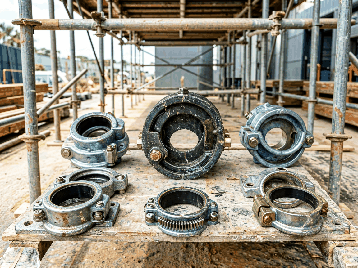
Scaffolding couplers and clamps are critical load-transfer components in temporary works systems, directly influencing structural stability, erection speed, and site safety. Their performance depends on precise dimensional compatibility, material strength, and connection integrity under dynamic loads. This guide explains the engineering considerations that determine suitability for specific construction, maintenance, and industrial access scenarios, enabling procurement teams to evaluate suppliers based on technical merit rather than generic claims.
The primary function of a coupler or clamp is to create a rigid, slip-resistant joint between scaffold tubes without damaging the parent material. Unlike welded or bolted permanent connections, these devices must achieve sufficient frictional resistance through clamping force alone, while allowing rapid assembly and disassembly. Key performance indicators include slip load resistance (typically measured in kN), torsional stiffness, and fatigue endurance under cyclic loading—factors governed by the interface geometry, bolt preload, and material properties of both the coupler and the tube.
Design standards such as EN 74, BS 1139, and ANSI/SSFI SC-100/500 define minimum performance thresholds for different coupler types (e.g., right-angle, swivel, sleeve, putlog). Compliance requires third-party testing to verify that the connection maintains integrity under specified load combinations, including shear, tension, and moment. Suppliers must provide traceable test reports demonstrating conformity—not merely claims of compliance—to mitigate procurement risk.
Most industrial-grade couplers and clamps are manufactured from forged or pressed steel, with material grade directly affecting strength-to-weight ratio and wear resistance. Common specifications include S355JR (EN 10025-2) for structural strength and DC01 (EN 10130) for formability in pressed components. The choice between forging and pressing influences grain flow, dimensional consistency, and susceptibility to stress concentrations—particularly at bolt holes and throat sections where crack initiation is most likely under repeated loading.
Surface treatment is not merely cosmetic; it directly affects corrosion resistance and friction characteristics. Hot-dip galvanizing (per EN ISO 1461) provides a zinc coating typically exceeding 55 µm, offering sacrificial protection in outdoor environments. Electrogalvanizing may be used for internal components but offers lower thickness (often 8–12 µm) and is less suitable for prolonged exposure. Some suppliers apply anti-slip coatings to the internal clamping surfaces—verified through friction coefficient testing—to enhance slip resistance without increasing bolt torque beyond safe limits.
In high-rise construction, couplers must resist wind-induced dynamic loads and differential settlement, favoring designs with high torsional rigidity and redundant load paths. For industrial maintenance in petrochemical or power generation facilities, where access is confined and loads are eccentric, swivel couplers with adjustable angles reduce the need for custom fabricated brackets. In shuttering and falsework applications, sleeve couplers are preferred for their ability to join tubes axially while resisting uplift forces from concrete pressure—requiring higher tensile strength in the clamping mechanism than standard right-angle types.
Environments with elevated temperatures (e.g., near furnaces or welding operations) may require couplers made from heat-resistant alloys or with thermal shielding, as standard steel can lose strength above 300°C. Similarly, in marine or chemical exposure zones, galvanization thickness may need augmentation, or alternative coatings like duplex systems (galvanized + epoxy) specified to extend service life. Suppliers should be able to provide material test certificates and coating thickness reports for critical projects.
Reliable suppliers implement statistical process control (SPC) on critical dimensions such as bolt hole diameter, throat width, and internal contour. Dimensional verification is typically performed using coordinate measuring machines (CMM) or calibrated gauges on first-off and periodic samples. Material traceability from mill certificate to finished part is essential—forging batches must be linked to test reports showing yield strength, tensile strength, and elongation. Non-conforming parts are segregated and documented, not reworked, to avoid hidden defects.
Load testing is conducted on representative samples from each production batch, not just initial validation. Slip tests are performed using calibrated hydraulic jacks applying load perpendicular to the tube axis, with measurements recorded at 0.1 mm slip increments. Results are compared against batch-specific requirements, not generic standards. Suppliers who provide actual test data—including date, sample ID, and observed failure mode—demonstrate a higher level of accountability than those offering only certificates of conformity.
| Coupler Type | Primary Use Case | Key Advantage | Limitation |
|---|---|---|---|
| Right-angle | Connecting tubes at 90° | Highest slip resistance in shear | Fixed angle limits flexibility |
| Swivel | Variable angle connections | Adaptable to irregular geometries | Lower torsional rigidity than fixed types |
| Sleeve | Axial tube joining | Resists tension and compression | Requires precise tube alignment |
| Putlog | Supporting putlogs or transoms | Optimized for load distribution | Limited to specific tube positions |
Note: Values are indicative; actual performance depends on tube material, bolt torque, and installation practice. Always verify supplier-specific test data for project-critical applications.





