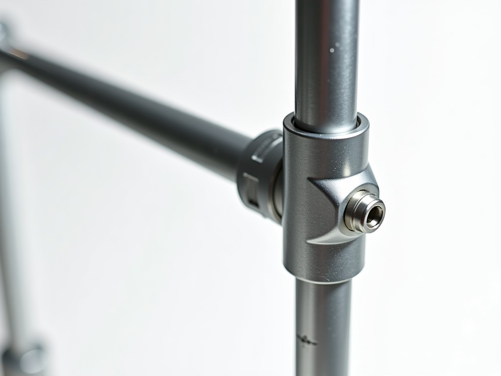
Adjustable U jacks are critical load-bearing components in modular scaffolding systems, providing vertical support and precise height adjustment for temporary structures. Their performance depends directly on correct sizing relative to expected loads, base plate dimensions, and threaded rod engagement length. Selecting the appropriate U jack size requires understanding the relationship between nominal height, adjustment range, and maximum safe working load under various site conditions.
The U-shaped top plate distributes load from scaffold standards or beams onto the threaded spindle, while the base plate ensures stability on uneven surfaces. Improper sizing can lead to insufficient thread engagement, eccentric loading, or premature wear—compromising structural integrity. This guide explains how to determine the correct U jack size based on engineering parameters rather than generic recommendations.
U jack size is defined by three interdependent measurements: nominal height (closed position), adjustment range (threaded travel), and base plate diameter. These values determine the usable height envelope and load capacity under ANSI/SSFI SC-100-5/07 or EN 1065 standards.
Nominal height refers to the minimum usable length when the jack is fully retracted, measured from the bottom of the base plate to the underside of the U-top. Adjustment range indicates how much the jack can extend via threaded spindle rotation, typically achieved through acme or trapezoidal thread profiles. Base plate diameter affects ground pressure distribution and resistance to lateral movement.
For example, a U jack with a 600 mm nominal height and 300 mm adjustment range provides a usable height range of 600–900 mm. Increasing nominal height without proportional increase in base size or thread diameter reduces buckling resistance. Manufacturers specify maximum extension limits to prevent thread disengagement or spindle deflection beyond elastic limits.
Safe working load (SWL) increases with U jack size due to larger cross-sectional area of the threaded spindle and improved buckling resistance. However, capacity is not linear—doubling spindle diameter increases theoretical strength by approximately four times, but real-world capacity depends on effective length, end restraints, and material yield strength.
A typical 38 mm diameter spindle with 600 mm nominal height may support 25 kN SWL when fully retracted, but this drops to 18 kN at full extension due to increased slenderness ratio. Larger base plates (e.g., 150 mm vs 100 mm diameter) reduce eccentric loading effects by providing greater resistance to tilt, indirectly improving usable load capacity on soft or uneven substrates.
Engineers must verify that the selected U jack size maintains adequate thread engagement—typically at least 1.5 times the spindle diameter—to prevent stripping under load. For high-rise scaffolding, longer jacks often require intermediate bracing or guying to address dynamic wind loads not accounted for in static SWL ratings.
Adjustable U jacks are manufactured in discrete size intervals to balance inventory efficiency with project flexibility. Common nominal heights range from 400 mm to 1000 mm, with adjustment spans between 200 mm and 400 mm. These increments align with typical scaffold lift heights (usually 2.0 m) allowing multiple jacks to achieve target elevations through combinations.
For facade work requiring frequent height adjustments, 500 mm nominal height with 300 mm adjustment offers versatility without excessive weight. Shorter jacks (400–450 mm) are preferred for mobile towers or low-height platforms where minimal retracted length is critical. Taller jacks (800–1000 mm nominal) serve deep foundations or basement shoring where significant under-slab clearance is needed.
Selection should begin with the maximum required working height, subtract the thickness of supported components (e.g., ledgers, transoms), then choose the smallest nominal size that allows achievement of that height within 80% of its adjustment range—preserving reserve for fine-tuning and avoiding operation near mechanical limits.
U jack size influences material grade selection due to differing stress concentrations. Smaller jacks (under 600 mm nominal) commonly use Q235 or S235JR carbon steel with 30–35 mm spindles, while larger sizes (700 mm+) often upgrade to Q345 or S355J2 to manage higher bending moments and prevent spindle deflection under eccentric loads.
Thread pitch and form also scale with size. Standard 38 mm spindles typically use 6 mm pitch acme threads, providing self-locking properties and wear resistance. Larger spindles (50 mm+) may adopt 8 mm pitch or square threads to increase load distribution per revolution and reduce torque requirements during adjustment under full load.
Base plate thickness increases proportionally with nominal height to prevent deformation—typically 6 mm for jacks under 700 mm, rising to 8–10 mm for taller versions. Hot-dip galvanizing thickness (minimum 55 microns per EN ISO 1461) remains consistent across sizes to ensure corrosion resistance proportional to surface area.
| Nominal Height (mm) | Adjustment Range (mm) | Typical Spindle Diameter (mm) | Base Plate Diameter (mm) | Max SWL at Mid-Range (kN) |
|---|---|---|---|---|
| 450 | 200 | 32 | 110 | 20 |
| 600 | 300 | 38 | 140 | 25 |
| 750 | 300 | 42 | 150 | 28 |
| 900 | 300 | 50 | 160 | 30 |
Values represent typical configurations; actual specifications vary by manufacturer and material grade. Custom sizes available upon request for projects requiring non-standard height envelopes or load profiles.
In concrete formwork, U jacks support vertical walers resisting lateral concrete pressure. Here, size selection prioritizes spindle stiffness over height range—longer, thinner spindles risk lateral deflection under cyclic loading, affecting formwork alignment. Shorter jacks with larger base plates often perform better despite less adjustment range.
For suspended scaffolding or swing stages, U jacks anchor to parapets or counterweights. Corrosion resistance becomes critical due to exposure, favoring hot-dip galvanized or stainless steel options even if nominal size could be reduced. The adjustment range must accommodate building facade irregularities and waterproofing membranes.
In shoring and reshoring applications, where jacks carry sustained loads for weeks or months, creep resistance of the threaded interface matters. Larger diameter spindles with coarse threads reduce unit pressure on the nut interface, minimizing wear and maintaining adjustability over time—favoring increased nominal size even if theoretical height needs could be met with smaller units.
Dimensional tolerances directly affect scaffold stability. Nominal height should vary no more than ±3 mm to prevent cumulative height errors in multi-level systems. Thread engagement length must be measurable and consistent—gauges verify minimum 15 mm engagement on 38 mm spindles to ensure load-bearing integrity.
Base plate flatness is critical; warping beyond 0.5 mm induces eccentric loading. Manufacturers use surface plates and feeler gauges to confirm compliance. Spindle straightness is verified by rolling on V-blocks—total indicator reading should not exceed 0.2 mm per 300 mm length to prevent binding or uneven wear during adjustment.
Thread pitch diameter and flank angle are checked using thread micrometers or optical comparators. Deviations increase torque requirements and risk of galling. Hardness testing (typically 120–180 HB for threaded zones) confirms adequate wear resistance without brittleness. All checks follow ISO 898-1 or equivalent fastener standards.
Selecting the correct scaffolding adjustable U jack size requires matching dimensional parameters to project-specific load cases, height requirements, and site conditions. Provide your maximum working height, expected load per support point, base surface conditions (e.g., soil, concrete, steel), and adjustment frequency for accurate sizing recommendations.
For complex configurations involving eccentric loads, dynamic forces, or non-standard connections, submit scaffold layout drawings or load diagrams. Our technical team evaluates spindle buckling, base plate settlement, and thread wear potential using established scaffolding design principles.
To initiate a quotation or request engineering consultation, share your project details via the contact form. Include any applicable standards (e.g., EN 12810, ANSI/ASSE A10.8) or client specifications that influence size or material selection.





