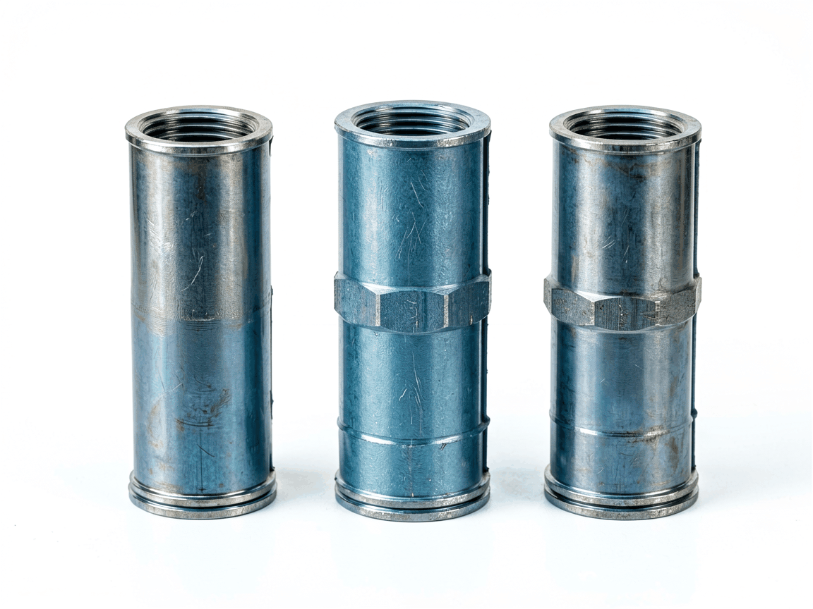
Scaffold tube sleeve connectors are mechanical couplings designed to join two sections of tubular scaffolding end-to-end without compromising structural continuity. They function by sliding over the exterior of adjacent tube ends and securing them through compressive force, typically via bolts, pins, or friction-based locking mechanisms. Unlike swivel or angle connectors, sleeve connectors maintain axial alignment, making them ideal for vertical or horizontal extensions where load path integrity is critical. Their primary purpose is to restore the full load-bearing capacity of the scaffold tube at the joint, ensuring that compressive, tensile, and bending forces are transferred efficiently between connected members.
The effectiveness of a sleeve connector depends on its ability to prevent relative movement between tubes under load while avoiding stress concentrations. Proper design ensures that the connector’s inner diameter matches the scaffold tube’s outer diameter with minimal clearance—typically 0.5 to 1.5 mm—to allow installation without galling while maintaining sufficient contact pressure. The connector length must be sufficient to develop adequate shear resistance along the tube-connector interface; industry practice often recommends a minimum length of 4 to 6 times the tube diameter to prevent pull-out or slip under design loads. Load transfer occurs primarily through friction and bearing stress, with bolts or pins providing clamping force to initiate and maintain this frictional resistance.
Material selection is governed by the required strength, environmental exposure, and compatibility with the scaffold tube. Common materials include structural carbon steel (e.g., S355JR) for general use and galvanized or stainless steel grades (e.g., EN 1.4301 / AISI 304) for corrosive environments. The connector’s wall thickness is engineered to exceed that of the scaffold tube to prevent localized deformation or cracking under cyclic loading. Finite analysis of similar couplings shows that stress concentrations are minimized when the connector features tapered or radiused ends, reducing the risk of fatigue initiation at the tube-connector interface during repeated loading cycles.
Scaffold tube sleeve connectors are manufactured to match standard scaffold tube diameters used internationally. The most common sizes correspond to 48.3 mm OD (1.5" NPS) and 60.3 mm OD (2" NPS) tubes, which are prevalent in modular scaffolding systems such as Cuplock, Kwikstage, and tube-and-coupler designs. Connector lengths typically range from 150 mm to 300 mm, with longer versions used in high-load applications or where splicing occurs in mid-span bending regions. Internal clearance is held to tight tolerances to ensure proper fit and prevent rattling or micro-movement under vibration.
| Parameter | Typical Value |
|---|---|
| Compatible Tube OD | 48.3 mm, 60.3 mm |
| Connector Length | 150–300 mm |
| Wall Thickness | ≥ Tube wall thickness (typically 3.2–5.0 mm) |
| Material Options | S355JR, Galvanized Steel, AISI 304/316 Stainless Steel |
| Fastening Method | Bolts (M10–M12), Pins, or Friction Grip |
| Surface Finish | Self-color, Hot-dip Galvanized, Powder Coated |
In temporary works, sleeve connectors are essential for extending scaffold standards (verticals) and ledgers (horizontals) to achieve required heights or spans without relying on overlapping tubes, which can create uneven load distribution and complicate bracing. They are particularly valuable in suspended scaffolding, where consistent tube alignment affects the safety of hoist mechanisms and platform stability. In falsework and formwork support systems, sleeve connectors allow for precise vertical adjustments during concrete pouring, enabling contractors to maintain design elevations despite foundation settlement or uneven ground.
Beyond temporary use, these connectors are increasingly adopted in semi-permanent structures such as pedestrian walkways, event platforms, and maintenance access systems where disassembly and reconfiguration are anticipated. Their ability to maintain full tube strength at the joint makes them preferable to sleeved couplings that rely solely on set-screws, which can loosen under vibration. In industrial settings, they are used to extend access towers around equipment requiring periodic inspection, where minimizing downtime favors modular, reconfigurable solutions over welded fabrications.
Dimensional verification is critical during manufacturing, particularly the inner diameter and length, as deviations directly affect fit and load capacity. Wall thickness uniformity is checked to ensure no weak points exist that could deform under compressive loads. For galvanized or coated connectors, coating adhesion and thickness are inspected to confirm corrosion protection meets EN ISO 1461 or equivalent standards. Mechanical properties of the base material are validated through mill test certificates, with tensile strength and elongation values verified against grade specifications.
Before shipment, connectors are assessed for straightness and end squareness, as bending or misalignment can induce secondary stresses in the assembled scaffold. Threaded fastener holes (if applicable) are gauged to ensure proper bolt engagement and prevent cross-threading. While non-destructive testing is not routine for standard connectors, visual inspection for cracks, laps, or incomplete forming is performed on 100% of units. Traceability is maintained through batch marking, enabling rapid response if field performance raises concerns.
While standard dimensions cover most scaffolding systems, certain projects require non-standard lengths, specialized materials, or modified end geometries. For example, connectors used in offshore environments may utilize duplex stainless steel (e.g., AISI 2205) with enhanced resistance to chloride-induced stress corrosion cracking. In high-temperature applications, such as temporary covers over industrial furnaces, heat-resistant alloys or ceramic-coated sleeves may be specified to maintain strength at elevated temperatures.
End modifications include swaged or reduced sections for insertion into confined spaces, or external flanges for bolting to structural steel or concrete anchors. Internal liners made of UHMW-PE or nylon can be added to reduce galling when connecting dissimilar metals or in high-cycle applications. These adaptations are developed collaboratively with engineering teams to ensure compatibility with global scaffolding standards such as EN 12810, EN 12811, or AS/NZS 1576, while addressing unique site constraints.





