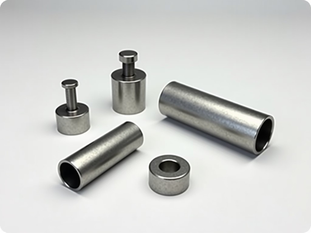
Scaffold joint sleeve coupler clamps are mechanical connectors used to join two scaffold tubes end-to-end, forming a continuous vertical or horizontal member. Unlike swivel or right-angle couplers, sleeve couplers rely on frictional grip between the coupler’s internal sleeve and the external tube surface, tightened by bolts or wedges to transfer axial and shear loads. They are commonly employed in tubular scaffolding systems where alignment, load continuity, and ease of assembly are critical for structural integrity.
The primary function of a sleeve coupler is to maintain load path continuity across a tube joint without introducing bending stress concentrations. When properly installed, the coupler distributes compressive and tensile forces through direct contact between the tube and the coupler’s inner surface, minimizing slip under service loads. This makes them suitable for load-bearing applications such as facade support, shoring, and access towers where joint strength must match or exceed the parent tube capacity.
Sleeve couplers consist of a cylindrical steel sleeve, typically split longitudinally, with internal gripping features such as serrations, knurls, or tabs to enhance friction. External lugs or ears provide leverage for tightening bolts or wedge mechanisms. The split design allows installation over the tube ends without disassembling the scaffold, while the gap between sleeve halves accommodates tolerance and ensures even clamping pressure when tightened.
Bolts are usually M12 or M16 grade 8.8, tightened to specified torque values to achieve sufficient clamping force. Some designs use wedge pins instead of bolts for faster installation, relying on mechanical interference to lock the sleeve halves together. The internal diameter is precision-machined to match nominal scaffold tube sizes (e.g., 48.3 mm OD), with a slight interference fit to prevent rotational movement under torque.
Surface treatments include hot-dip galvanizing per ISO 1461 or electro-galvanizing for corrosion resistance in outdoor environments. Uncoated steel versions are available for temporary indoor use or where painting is specified. The coupler’s length typically ranges from 100 mm to 150 mm, providing sufficient overlap to develop full shear and tensile capacity without excessive protrusion that could interfere with adjacent components.
Scaffold joint sleeve couplers are manufactured from structural carbon steel, commonly grades such as S275JR or S355JR, selected for yield strength, ductility, and weldability if repairs are needed. The material must withstand repeated tightening cycles without cracking or thread stripping. Mechanical properties are verified through mill test certificates, with typical minimum yield strength of 275 MPa and tensile strength of 430–580 MPa depending on grade.
The coupler’s design must ensure that the tube fails before the coupler slips or deforms excessively under load. This is achieved by sizing the clamping area and bolt strength so that the slip load exceeds the tube’s characteristic capacity. For a 48.3 mm x 3.2 mm steel tube, the characteristic tensile capacity is approximately 20–25 kN; a properly designed sleeve coupler should resist slip at loads above 30 kN when tested per EN 74 or equivalent standards.
Elongation and toughness are important for impact resistance, especially in cold climates. Couplers intended for use below 0°C may require normalized or fine-grained steel to avoid brittle fracture. Manufacturing processes such as cold forming or forging are preferred over casting to ensure grain flow and defect-free sections in high-stress areas like the bolt holes and splitting line.
Sleeve couplers are primarily designed to resist axial tension and compression. Shear capacity is secondary but still significant, particularly in diagonal bracing or moment-resisting joints. The slip resistance depends on clamping force, friction coefficient between tube and sleeve, and contact area. Typical static slip resistance for a galvanized coupler with serrated interior and M12 bolts torqued to 80 Nm ranges from 25–35 kN in tension and 15–20 kN in shear, depending on tube surface condition.
Cyclic loading can reduce slip resistance over time due to micro-movement and fretting. For applications involving vibration or repeated load reversals (e.g., formwork or shuttering), couplers with higher initial clamping force or mechanical locking features (e.g., wedge pins) are recommended. Design standards such as BS 1139 or EN 74 specify minimum performance criteria, including proof load tests at 1.5 times the working load and ultimate load tests to failure.
Deflection at working load is typically less than 0.5 mm, ensuring minimal joint movement that could affect scaffold alignment or decking stability. Excessive deflection indicates insufficient clamping force, worn components, or mismatched tube tolerance. Users should inspect couplers for ovalization, thread damage, or corrosion before reuse, as these reduce effective clamping area and increase slip risk.
Scaffold joint sleeve coupler clamps are used wherever scaffold tubes must be joined in-line to create longer members without compromising strength. In facade scaffolding, they enable continuous vertical standards that transfer wind and dead loads to the base without intermediate splices that could weaken the system. In shoring and falsework, they connect longitudinal beams or props to form uninterrupted load paths from slab to soffit, critical for maintaining deflection limits during concrete pours.
They are also employed in access towers and stair scaffolds where vertical continuity is required for ladder or stair unit alignment. Unlike couplers that offset the joint (e.g., putlog or swivel couplers), sleeve couplers keep the tube axis concentric, avoiding eccentricity that could induce bending in tall structures. This makes them preferable in applications where P-delta effects or lateral stability are design concerns.
In modular scaffolding systems, sleeve couplers allow rapid extension of pre-assembled frames or towers. Their simplicity—requiring only a wrench or hammer for installation—supports fast erection and dismantling, reducing labor time. However, they are not suitable for joints requiring angular adjustment; for those, swivel or right-angle couplers must be used in conjunction with sleeve couplers to maintain system flexibility.
Correct installation begins with verifying tube cleanliness and straightness. Oil, paint, mud, or rust on the tube surface reduces friction and must be removed before inserting the coupler. The tube ends should be cut square and free of burrs to ensure even contact with the sleeve interior. Misaligned or oval tubes can cause uneven pressure distribution, leading to premature slip or coupler deformation.
The coupler is placed over the tube joint so that each tube end inserts approximately halfway into the sleeve. Bolts are then tightened incrementally and alternately to ensure uniform pressure. Torque should be applied using a calibrated wrench to the manufacturer’s specified value—typically 60–100 Nm for M12 bolts—since under-torquing reduces clamping force, while over-torquing risks thread stripping or sleeve cracking.
Inspection before reuse includes checking for: bolt thread integrity, sleeve cracks (especially at the split ends), elongation of bolt holes, corrosion pitting, and internal sleeve wear. Any coupler showing signs of plastic deformation, cracking, or excessive wear should be removed from service. Galvanized coatings should be inspected for peeling or white rust; minor surface oxidation is acceptable, but red rust indicating base metal corrosion requires evaluation.
| Feature | Sleeve Coupler | Right-Angle Coupler | Swivel Coupler |
|---|---|---|---|
| Primary Function | Axial load transfer (tension/compression) | Moment transfer at 90° | Variable angle connection |
| Load Path Continuity | High (inline joint) | None (offset joint) | Low (eccentric joint) |
| Installation Time | Moderate (bolt tightening) | Fast (single bolt) | Moderate (angle adjustment + bolt) |
| Adjustability | None (fixed inline) | None (fixed 90°) | Full 0–360° |
| Typical Slip Resistance (Tension) | 25–35 kN | Not applicable | Not applicable |
This table illustrates that sleeve couplers excel in maintaining axial load continuity, a critical factor in vertical and horizontal load-bearing scaffolding members. Right-angle and swivel couplers serve different geometric functions but do not provide inline joint strength. Selecting the correct coupler type depends on the structural requirement: use sleeve couplers for load-path continuity, right-angle couplers for ledger-to-transom connections, and swivel couplers for diagonal bracing or irregular geometries.
While standard sleeve couplers suit nominal 48.3 mm scaffold tubes, variations exist for different tube diameters (e.g., 42.4 mm, 60.3 mm) or wall thicknesses. Custom lengths can be provided to accommodate specific overlap requirements or to integrate with proprietary scaffolding systems. Internal surface modifications—such as deeper serrations, axial grooves, or inserted friction rings—are available to increase slip resistance in high-load or dynamic applications.
Bolt specifications can be adjusted: higher tensile grades (e.g., 10.9) for increased clamping force, stainless steel (A2 or A4) for corrosive environments, or coated bolts to prevent galling. Alternative locking mechanisms include wedge pins, toggle bolts, or cam levers for tool-free installation where speed is prioritized over reusability. Finish options extend beyond galvanizing to include powder coating for color coding or zinc-nickel plating for enhanced corrosion resistance in marine or industrial settings.
Marking options such as laser etching, stamping, or colored inserts help with inventory control, traceability, or rental fleet management. Custom packaging—such as bulk packs, polybags with desiccant, or reusable crates—can be arranged based on order volume and logistics requirements. All customizations are subject to minimum order quantities and engineering review to ensure compatibility with intended load conditions and safety factors.
Manufacturing begins with certified raw material, verified via mill test reports for chemical composition and mechanical properties. Dimensional checks are performed at multiple stages: inner diameter, outer diameter, length, bolt hole position, and split width. Critical features such as serration depth and angle are inspected using profilometers or optical comparators to ensure consistent frictional performance.
Mechanical validation includes proof load testing on a sample basis, where couplers are assembled onto tubes and subjected to incremental tensile and shear loads until slip or deformation occurs. Results are compared against design benchmarks. Non-destructive testing such as magnetic particle inspection may be used for high-stress areas like bolt holes and split ends to detect surface cracks invisible to visual inspection.
Final inspection includes visual assessment for coating uniformity, thread cleanliness, and absence of burrs or sharp edges. Functional checks involve assembling and disassembling the coupler multiple times to verify smooth operation and consistent torque response. Documentation such as test reports, material certificates, and compliance statements (e.g., to EN 74 or ANSI/ASSE A10.8) are provided upon request to support procurement due diligence.





