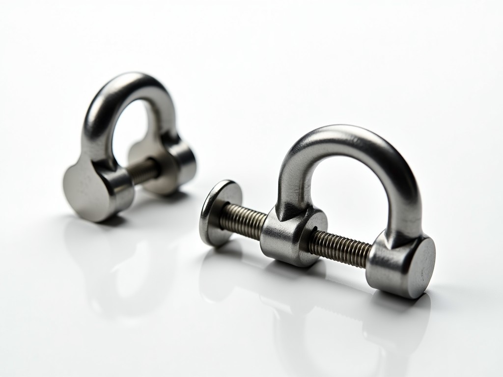
Scaffold girder hook clamp couplers are engineered to securely connect scaffold tubes to structural steel girders, beams, or columns where traditional base plates or sole plates cannot be used. They provide a load-bearing interface between temporary access systems and permanent building structures, enabling safe erection of working platforms at elevated levels. These couplers are specifically designed for scenarios requiring vertical load transfer, lateral stability, and resistance to slip under dynamic site conditions.
Unlike standard right-angle or swivel couplers that connect tube-to-tube, girder hook clamps attach directly to the flange or web of steel members, distributing forces through engineered gripping mechanisms. Their design accommodates varying flange thicknesses and profiles while maintaining alignment tolerances critical for scaffold stability. Proper selection depends on girder geometry, anticipated loads, and environmental exposure, making technical specification essential before procurement.
The primary function of a girder hook clamp coupler is to transfer vertical and lateral loads from the scaffold tube to the host steel member without damaging the girder finish or compromising structural integrity. This is achieved through a combination of clamping force, frictional resistance, and positive mechanical engagement. The hook component engages the girder flange edge, while the threaded bolt or toggle mechanism applies perpendicular pressure to create a secure lock.
Load capacity is determined by the cross-sectional area of the hook, bolt grade, and contact surface pressure. Typical working load limits (WLL) range from 2.5 kN to 5.0 kN per coupler when installed correctly on structural steel with minimum yield strength of 250 MPa. Exceeding these limits risks permanent deformation of the hook or slippage under cyclic loading. Manufacturers specify WLL based on static testing; dynamic factors such as wind or impact must be applied per local scaffolding codes (e.g., EN 12811, AS/NZS 1576).
Corrosion resistance is achieved through hot-dip galvanizing per ISO 1461 or equivalent zinc coating thickness (typically 55–85 µm). This provides sacrificial protection in outdoor environments, extending service life in humid or chemically exposed conditions. Alternative finishes like sherardizing or mechanical plating may be offered for specific applications where dimensional tolerances are critical.
Girder hook clamps are forged or machined from structural steel grades such as S275JR or S355JR to balance strength, ductility, and weldability if repair is needed. The hook profile is contoured to match common flange thicknesses (typically 8–25 mm) while avoiding stress concentrations at the bend radius. Internal surfaces are machined or ground to ensure flat contact with the girder web or flange, maximizing frictional resistance.
The clamping mechanism typically uses a Grade 8.8 or 10.9 hex bolt with nut and washer, pre-torqued to specified values (often 80–120 Nm) to generate sufficient clamping force. Some designs incorporate a cam-action toggle or wedge system for faster installation without torque tools, though these may require periodic retightening checks. U-bolt variants exist for asymmetric girder profiles but are less common in standard scaffolding applications.
Tube compatibility is standardized to 48.3 mm outer diameter scaffold tubes, with the coupler socket machined to precise tolerances (usually ±0.5 mm) to prevent play while allowing for thermal expansion. Inspection points include verifying bolt torque, checking for hook deformation, and ensuring no gap exists between the clamp body and girder surface after installation.
These couplers are indispensable in retrofit, maintenance, and new construction projects where scaffold towers must be anchored to building steelwork without penetrating or modifying the primary structure. Common scenarios include attaching access platforms to crane girders in manufacturing facilities, securing scaffolding to tram or rail support beams during infrastructure upgrades, and creating suspended work stages beneath bridges or overpasses.
In industrial plants, girder hook clamps enable safe access to piping, ductwork, and equipment mounted on elevated steel frames where ground-based scaffolds are obstructed by machinery or process lines. Their non-invasive nature preserves fireproofing coatings, galvanized finishes, and architectural elements that would be damaged by drilling or welding temporary attachments.
They are also used in shoring and falsework systems to support formwork beams during concrete pours, particularly when the soffit is too high for traditional jack systems. By transferring load directly to the primary structure, they reduce the need for extensive falsework legs and improve site congestion.
Correct installation begins with verifying girder flange thickness and profile compatibility. The hook must fully engage the flange edge without overhang or binding. The coupler body should sit flush against the girder web or flange with no twisting or tilting. Misalignment reduces contact area and increases stress on the bolt, risking premature failure.
Bolt torque must be applied using a calibrated wrench to the manufacturer’s specification. Under-torquing allows slip under load; over-torquing can yield the bolt or deform the girder flange. After initial loading (e.g., first 24 hours or after 5% of design load), retorque checks are recommended as settling may occur. Visual inspections should confirm no gaps, cracks, or permanent deformation in the hook or clamp body.
Scaffold tubes connected to the coupler must be plumb and level to avoid eccentric loading. Couplers should not be used as beam clamps for suspending loads unless explicitly rated for such use. All installations must comply with local scaffolding regulations, which often require independent verification by a competent person before use.
| Feature | Standard Hook Clamp | Wide-Throat Hook Clamp | Toggle-Action Clamp |
|---|---|---|---|
| Typical Flange Range | 8–18 mm | 18–28 mm | 8–22 mm |
| Clamping Mechanism | Hex bolt & nut | Hex bolt & nut | Cam toggle |
| Installation Time | Moderate (requires torque wrench) | Moderate | Fast (no tools) |
| Retorque Required? | Yes, after initial load | Yes | Periodic checks advised |
| Typical WLL (kN) | 3.0–4.0 | 2.5–3.5 | 3.0–4.5 |
| Best For | Standard I-beams, H-sections | Wide-flange columns, heavy sections | Rapid erection/dismantling cycles |
Values are typical; actual capacity depends on girder material, installation quality, and local safety factors. Consult manufacturer data sheets for project-specific ratings.
Manufacturing begins with certified raw material traceable to mill test reports (MTRs). Each batch undergoes dimensional inspection using calibrated gauges to verify hook radius, bolt hole alignment, and socket concentricity. Mechanical properties are validated through spot testing of tensile strength and yield point on sacrificial samples from each production lot.
Surface coating thickness is measured via magnetic induction or gravimetric methods to ensure compliance with ISO 1461. Adhesion testing (e.g., cross-hatch per ASTM D3359) confirms coating integrity under stress. Final assembly includes functional testing where clamps are installed on calibrated girder simulators and loaded to proof load (typically 1.5× WLL) to verify no slip or deformation.
Each coupler is marked with laser-engraved or stamped identifiers including manufacturer code, batch number, size rating, and CE or UKCA conformity where applicable. This enables full traceability from raw material to end use, supporting inspection audits and incident investigations. Packaging includes corrosion-inhibiting film and stackable pallets to prevent deformation during transit and storage.
For technical inquiries, load calculations, or custom configurations based on specific girder profiles or site conditions, contact our engineering team to discuss your project requirements.
Request Technical Specification or Quotation




