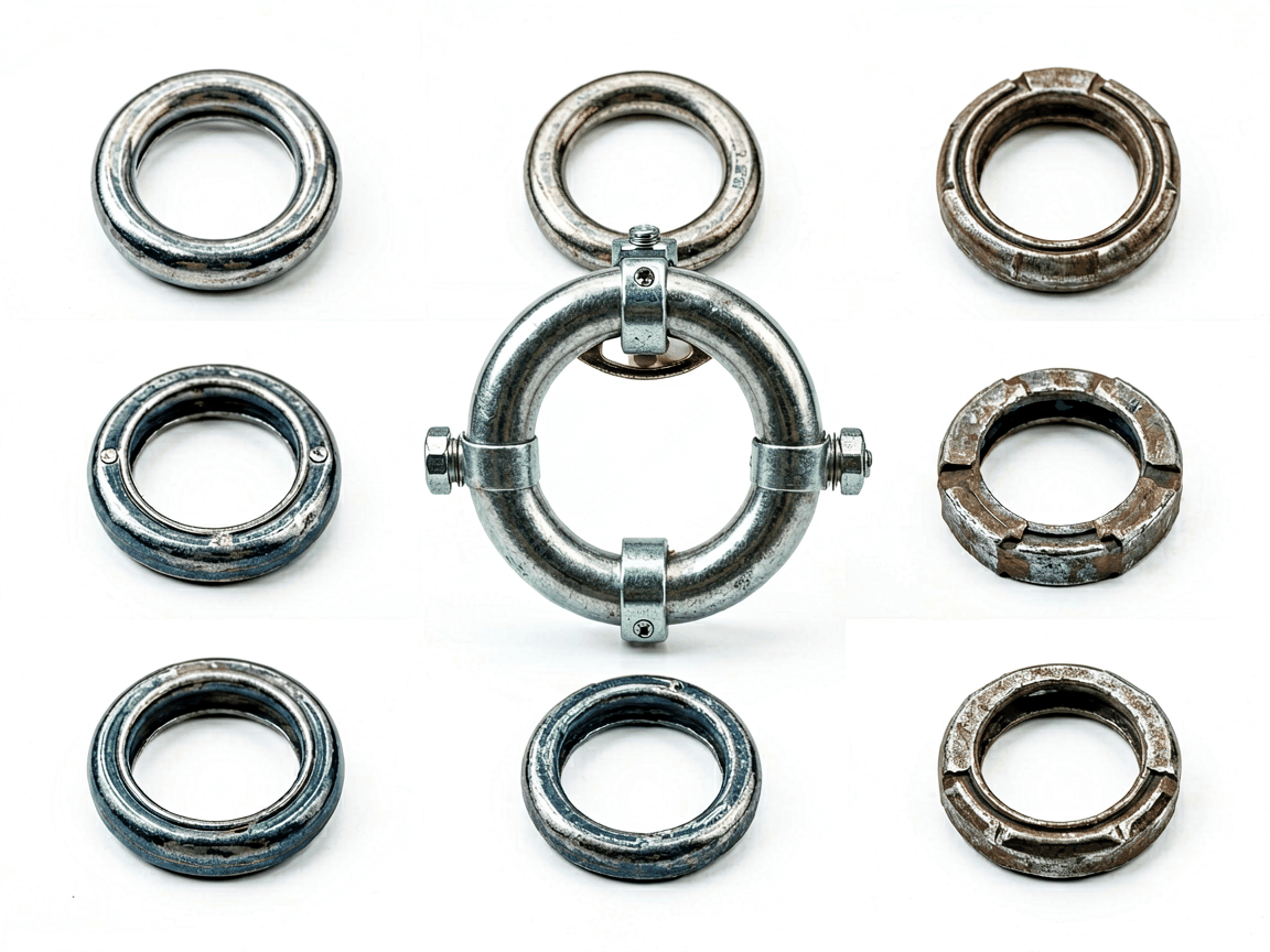
Ring lock scaffolding systems are modular temporary structures designed for rapid assembly and disassembly in construction, maintenance, and industrial access applications. Their defining feature is the ring-shaped connector welded to vertical standards, which accepts horizontal ledgers and diagonal braces via wedge locks, creating a rigid, self-locking joint without the need for bolts or pins. This design enables high load capacity, precise alignment, and repeatable setup across multiple project phases.
The system’s geometry ensures that all connected members transfer loads primarily through axial compression and tension, minimizing bending moments at joints. This efficiency allows ring lock scaffolding to support heavier loads per bay compared to tube-and-clamp or frame systems, making it suitable for high-rise buildings, bridges, shipyards, and heavy industrial plants where safety and speed are critical. The modularity also reduces on-site labor time by up to 50% compared to traditional methods.
A complete ring lock system consists of standardized vertical standards, horizontal ledgers, diagonal braces, base jacks, and specialized adapters. Each component is engineered to interface precisely with the ring lock node, ensuring consistent geometry and load distribution. Vertical standards are typically produced in 0.5m increments from 0.5m to 3.0m, allowing flexible height configuration. Ledgers and braces are available in standard bay lengths ranging from 0.6m to 3.0m, with diagonal braces providing lateral stability in both planes.
| Component | Function | Typical Length Range | Material Specification |
|---|---|---|---|
| Vertical Standard | Primary load-bearing member; transfers vertical loads to foundation | 0.5m – 3.0m (in 0.5m increments) | Q345B steel, hot-dip galvanized |
| Horizontal Ledger | Connects standards horizontally; supports working platforms | 0.6m – 3.0m | Q345B steel, hot-dip galvanized |
| Diagonal Brace | Provides lateral stability; prevents racking under wind or seismic loads | 1.0m – 3.0m | Q345B steel, hot-dip galvanized |
| Base Jack | Adjusts for uneven foundations; transfers load to ground or sleeper | Adjustable range: 0–300mm | Q235 steel body, threaded rod, galvanized |
| U-Head Jack | Supports beams or formwork; allows vertical adjustment at top of scaffold | Adjustable range: 0–300mm | Q235 steel body, threaded rod, galvanized |
The ring lock node itself is a critical engineering feature: a forged or pressed steel ring with multiple receptacles (typically 4–8) spaced at 50mm intervals, allowing ledgers and braces to connect at precise angles. Wedge locks, inserted through the ring and tightened with a hammer, create a mechanical interlock that resists rotation and withdrawal under load. This connection method achieves joint efficiencies exceeding 90% of the member’s yield strength, significantly higher than friction-based couplers.
Structural components are manufactured from high-strength low-alloy (HSLA) steels such as Q345B, which offers a minimum yield strength of 345 MPa and tensile strength between 470–630 MPa. This material choice allows for thinner wall sections without sacrificing load capacity, reducing component weight by up to 20% compared to carbon steel equivalents while maintaining durability. The chemical composition includes controlled levels of manganese, silicon, and trace alloys to enhance hardenability and toughness.
All components undergo hot-dip galvanization per ISO 1461, applying a zinc coating typically ranging from 55 to 85 microns thick. This provides sacrificial protection against corrosion, extending service life in outdoor and humid environments to 15+ years with minimal maintenance. The coating thickness is verified via magnetic induction testing during quality control, ensuring uniformity across complex geometries such as ring nodes and threaded adjusters.
For specialized applications — such as offshore platforms, chemical plants, or tunnels with high chloride exposure — components may be specified with duplex coatings (galvanized plus epoxy) or manufactured from stainless steel grades like 304L or 316L. These options increase initial cost but eliminate maintenance cycles in aggressive environments, offering lower total cost of ownership over 20+ year lifespans.
The axial load capacity of a ring lock standard depends on its length, end conditions, and bracing configuration. A 2.0m standard with both ends fixed and intermediate bracing at 1.0m intervals can safely support up to 25 kN per leg under Eurocode EN 12810-1 criteria. When used in a full bay configuration with ledgers and diagonal braces, the system distributes loads such that no single joint exceeds 80% of its design capacity under uniform loading, ensuring redundancy and progressive failure resistance.
Lateral stiffness is primarily governed by diagonal brace placement. In a standard 1.8m x 1.8m bay, installing diagonal braces on all four sides at 45° angles increases lateral load resistance by over 300% compared to an unbraced bay. This stiffness minimizes sway under wind loads (up to 1.2 kN/m²) and dynamic loads from equipment or personnel movement, enhancing worker safety and precision for tasks like concrete pouring or welding.
Deflection limits are critical for formwork and facade access. Under a uniformly distributed load of 2.0 kN/m² (typical for concrete formwork), a 3.0m bay with proper bracing exhibits vertical deflection under 10mm — well within the L/300 limit for formwork stability. This performance is achieved through the system’s inherent triangulation and the high shear resistance of the ring lock joints, which prevent slippage even under cyclic loading.
While standard components cover 90% of common applications, ring lock systems are frequently adapted for unique geometries or load demands. Custom solutions include tapered standards for conical structures, swivel couplers for non-orthogonal connections, and reinforced ledgers for heavy equipment support. These modifications are engineered using finite element analysis to ensure compatibility with the base system’s load paths and joint integrity.
Length adjustments beyond standard increments are achieved through sleeve couplers or overlapping joints, though these require additional bracing to maintain stiffness. For suspended or cantilevered applications, specialized brackets and anchor plates are designed to transfer loads back to the primary structure, with connection details verified through pull-out and shear testing. All custom parts maintain the same ring lock interface to ensure interchangeability with stock components.
Surface treatments can also be tailored: powder coating in specific colors for identification or aesthetic requirements, or anti-static coatings for electronics manufacturing environments. Threaded components like base jacks may be supplied with trapezoidal or ACME threads for improved wear resistance under frequent adjustment. These options are available upon request and are subject to minimum order quantities based on tooling requirements.
Manufacturing begins with precision cutting of steel tubes to specified lengths, followed by ring forming via hydraulic pressing or robotic welding. The ring lock node is subjected to concentricity checks, ensuring the centerline deviation remains under 0.5mm to prevent eccentric loading. Wedge locks are forged from alloy steel, heat-treated to HRC 40–45, and dimensionally inspected to guarantee consistent interference fit with the ring receptacles.
Post-galvanizing, components undergo adhesion testing (ISO 2409) and coating thickness verification. Load testing is performed on sample batches using hydraulic actuators to simulate ultimate and service loads, with acceptance criteria based on EN 12811-1. Non-destructive testing such as magnetic particle inspection is applied to welds on high-stress nodes to detect surface-breaking defects. Traceability is maintained via laser etching or stamping, linking each component to its material certificate and production batch.
Packaging is designed to prevent damage during transit and storage. Components are bundled in hexagonal or square packs using steel straps, with protective plastic end caps on threaded elements. Standard bundles weigh between 25–40kg for manual handling, while full pallets (typically 1.2m x 1.0m) hold 20–30 bundles and are stretch-wrapped and corner-protected for forklift handling. Export shipments include moisture-barrier lining and desiccant packs to prevent condensation-related staining during ocean freight.
Ring lock scaffolding excels in high-rise construction due to its ability to maintain vertical alignment over 50+ stories with minimal cumulative error. The self-locking joints resist loosening from vibration caused by pumps, mixers, or elevator installation, reducing the need for frequent retightening. This reliability makes it preferred for core-and-shell construction where access must remain uninterrupted for months.
In bridge construction and maintenance, the system’s high strength-to-weight ratio allows for efficient erection over water or traffic lanes using cantilever launch techniques. Diagonal bracing configurations can be adapted to follow the curvature of box girders or arch ribs, providing continuous worker access without interfering with structural components. The modularity also enables rapid reconfiguration as construction progresses from substructure to deck work.
Industrial plants utilize ring lock scaffolding for turnaround maintenance in refineries, chemical facilities, and power stations. The system’s resistance to chemical splash and ease of decontamination make it suitable for environments where hydrocarbons or acids are present. Its ability to support heavy loads — such as boiler tubes or heat exchanger bundles — allows it to double as both access platform and temporary storage, reducing crane lifts and improving logistics efficiency.
Shipyards and offshore platforms benefit from the system’s performance in salt-laden air and its compatibility with suspended stages and personnel nets. The consistent geometry facilitates integration with automated climbing systems and motorized work platforms. In confined spaces like tank interiors or penstocks, compact bay sizes (as small as 0.6m x 0.6m) allow access where larger frame systems cannot fit, while the high load capacity supports ventilation equipment and lighting rigs.
Ready to discuss your project requirements?
Contact our technical team for a detailed quotation, customization options, or load capacity calculations specific to your site conditions.
Request Technical Consultation




