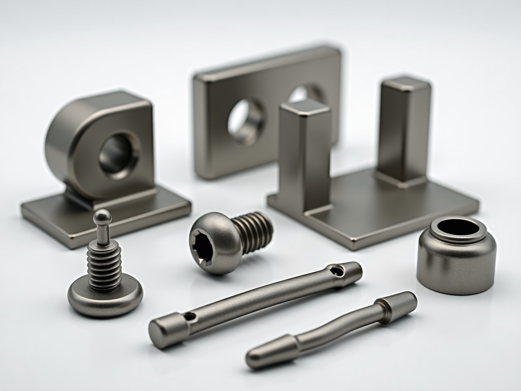
Putlog scaffolding structure accessories are specialized components designed to secure, reinforce, and interface putlog tubes with the primary scaffold framework. These accessories ensure load transfer integrity, lateral stability, and compatibility between tube diameters and coupling systems used in temporary works.
Unlike general-purpose scaffold fittings, putlog accessories are engineered to accommodate the specific geometric and mechanical demands of putlog connections—where the scaffold tube bears against a building structure or formwork, transferring loads through bearing, friction, or mechanical interlock.
Putlog accessories fall into distinct categories based on their mechanical role in the scaffolding system. Each type addresses a specific load path or installation requirement.
Material choice directly affects durability, corrosion resistance, and load capacity. Common materials are selected based on environmental exposure and re-use cycles.
| Component Type | Typical Material | Surface Treatment | Corrosion Resistance (ISO 12944) |
|---|---|---|---|
| Putlog Brackets | S355JR Steel | Hot-dip Galvanized (Zn 55µm) | C3-Medium |
| Putlog Couplers | S235JR Steel | Hot-dip Galvanized (Zn 55µm) | C3-Medium |
| Putlog Base Plates | S275JR Steel | Hot-dip Galvanized (Zn 55µm) | C3-Medium |
| Putlog End Caps | HDPE (UV Stabilized) | None (inherent) | Immune to electrochemical corrosion |
| Putlog Adapters | S355JR Steel | Hot-dip Galvanized (Zn 55µm) | C3-Medium |
For marine or industrial environments, stainless steel (AISI 304/316) or duplex grades are available upon request. Non-metallic options like reinforced nylon are used for non-load-bearing protection elements.
Putlog accessories must match the nominal tube diameter and coupling interface standards of the host scaffold system. Mismatch can lead to slip, fretting, or premature failure.
| Nominal Tube Size (mm) | Compatible Putlog Coupler Type | Typical Bracket Thickness (mm) | Standard Hole Pattern (mm) |
|---|---|---|---|
| 48.3 x 3.2 (1.5" SCH 40) | Right-Angle Coupler (BS 1139) | 6 | 50 x 50 |
| 48.3 x 4.0 (1.5" SCH 80) | Right-Angle Coupler (EN 74) | 8 | 50 x 50 |
| 50.8 x 3.0 (2" SCH 40) | Swivel Coupler (Modified) | 6 | 60 x 60 |
| 60.3 x 3.6 (2.5" SCH 40) | Heavy-Duty Putlog Coupler | 10 | 70 x 70 |
Custom diameters, wall thicknesses, or hole patterns are available for specialized formwork or retrofit applications. Tolerances follow ISO 2768-m for machined features and EN 1090-2 for welded components.
Putlog accessories are designed to resist specific force combinations: axial compression from the putlog tube, shear from lateral loads, and moment from eccentric loading. Capacity depends on material grade, cross-section, and connection type.
Finite element analysis (FEA) is commonly used to validate stress distribution in complex brackets. Physical testing follows EN 12810/EN 12811 for scaffolding components, with safety factors of 1.6 for yield and 2.0 for ultimate.
Corrosion protection is critical for re-use cycles and safety. Hot-dip galvanizing per EN ISO 1461 provides sacrificial protection, with coating thickness directly influencing service life.
| Coating Thickness (µm) | Expected Life (Years) in C3 Environment | Maintenance Inspection Interval |
|---|---|---|
| 40 | 5–7 | Annual |
| 55 | 7–10 | Biennial |
| 70 | 10–15 | Every 2 Years |
Repair galvanizing is possible per ASTM A780 for minor damage. Powder coating or duplex systems (galvanize + paint) are available for architectural applications requiring specific color or UV resistance.
Consistent performance relies on controlled manufacturing and inspection. Key control points include material certification, dimensional verification, and coating integrity.
Load testing is conducted on a sampling basis per EN 12811-1:2003, Annex B. Non-conforming items are segregated and reworked or scrapped based on root cause analysis.
Putlog accessories are essential in scenarios where scaffolding must integrate with existing structures or formwork without imposing excessive loads or requiring penetrations.
In each case, the accessory must be selected based on the substrate’s load-bearing capacity, the duration of exposure, and the required re-use cycles. Engineering review is recommended for loads exceeding 10 kN per connection.
Standard accessories cover most common scenarios, but project-specific constraints often require tailored solutions. Customization is driven by interface geometry, load demands, or access limitations.
Lead times for standard items are typically 2–3 weeks. Custom designs require 4–6 weeks for approval, prototyping, and production, depending on complexity and material availability. Technical datasheets and installation guides are provided upon request.
For technical specifications, customization inquiries, or to request a quotation, contact our engineering team.
Request Information




