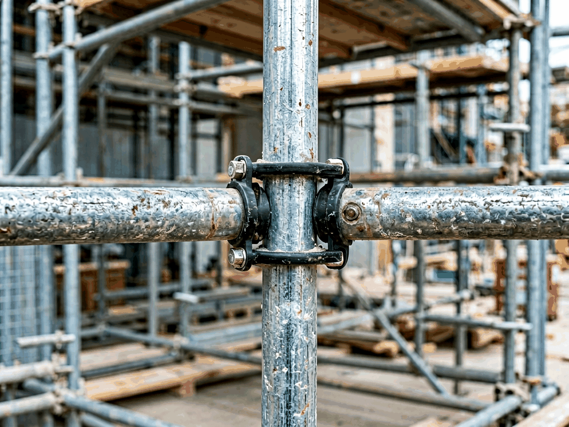
A putlog coupler clamp is a fundamental scaffolding component designed to securely connect horizontal putlog tubes to vertical standards (uprights) at right angles. Unlike swivel or right-angle couplers that join tube-to-tube, putlog couplers are specifically engineered to support the transfer of loads from putlogs—shorter horizontal members that bear the working platform or formwork—into the main scaffold structure. This connection method is essential in bricklaying, masonry, and formwork applications where putlogs must be anchored firmly to the scaffold frame to safely carry distributed loads from bricks, blocks, or wet concrete.
The clamp operates by encircling the vertical standard with a C-shaped body and tightening a threaded bolt or nut against the putlog tube, creating a friction-based grip that resists both axial and lateral forces. Proper installation ensures that the putlog remains perpendicular to the standard and does not slip under load, which is critical for maintaining scaffold integrity and preventing platform displacement. The design avoids welding or permanent fixation, allowing for rapid assembly, adjustment, and disassembly—key advantages in modular scaffolding systems used across temporary construction projects.
Putlog coupler clamps are typically manufactured from hot-rolled or cold-formed steel grades such as S235JR or Q235, selected for their yield strength (typically 235–250 MPa) and ductility, which allows the clamp to deform slightly under overload before failure—providing a visible warning sign rather than sudden brittle fracture. The steel is often processed through pressing or forging to achieve the precise C-channel geometry required to match standard scaffold tube diameters (commonly 48.3 mm OD).
Surface treatment is a critical factor in service life, particularly in outdoor or humid environments. Most clamps undergo hot-dip galvanizing per ISO 1461 or EN ISO 10684, applying a zinc coating of 55–85 µm thickness to provide sacrificial corrosion protection. This coating significantly extends service life compared to untreated or electro-galvanized alternatives, especially in coastal or industrial atmospheres where chloride exposure accelerates rust. Some variants may feature powder coating for aesthetic or specialized chemical resistance, though galvanizing remains the dominant choice for structural scaffolding due to its durability and impact resistance.
The tightening mechanism usually consists of a high-tensile steel bolt (Grade 8.8 or equivalent) and a captive nut, often with a washer to distribute clamping force and prevent damage to the tube surface. Torque requirements typically range from 50 to 70 Nm to achieve sufficient clamping force without over-stressing the tube or stripping threads. The design ensures that the bolt head or nut remains accessible for tools (e.g., spanner or ratchet) even when installed in tight spaces between standards and putlogs.
The primary load path in a putlog coupler is shear forces transferred from the putlog into the standard via the clamp’s gripping action. Engineering assessments typically consider two limit states: slip resistance under service loads and ultimate strength under factored loads. Slip resistance depends on the normal force generated by bolt tension and the coefficient of friction between the clamp interior and the tube surface—affected by surface condition, coatings, and contamination (e.g., mud, paint, or grease).
Under ultimate limit state, the clamp must resist deformation or pull-out of the putlog tube. Test data from recognized scaffolding standards (e.g., EN 74, BS 1139, or ANSI/SSFI SC-100) indicate that compliant putlog couplers typically withstand characteristic loads of 2.2 kN per tube in shear, with a design resistance of approximately 1.5 kN after applying partial safety factors. These values assume correct installation, undamaged components, and clean, dry tube interfaces. Any deviation—such as bent tubes, corroded surfaces, or improper bolt torque—can significantly reduce capacity.
It is important to note that putlog couplers are not designed to resist significant moment loads or to replace base plates or sole boards. Their function is strictly to transfer axial and shear loads from the putlog into the scaffold standard. Using them to support cantilevered loads, heavy equipment, or as moment-resisting joints violates their intended design and poses safety risks. Engineers must verify that the scaffold design accounts for putlog spacing, load distribution, and standard capacity in accordance with local scaffolding regulations (e.g., OSHA 1926 Subpart L in the U.S. or TG20:13 in the UK).
Putlog coupler clamps are most commonly employed in bricklaying scaffolding, where putlogs extend from the scaffold frame to support the outer edge of the working platform as the wall rises. As each course of bricks is laid, putlogs are repositioned upward, and the couplers allow quick release and reattachment without disturbing the main scaffold structure. This cyclical use demands components that endure repeated assembly cycles without galling, thread damage, or loss of clamping force.
In concrete formwork systems, putlog couplers serve a similar role by supporting putlogs that carry transverse beams or joists holding sheathing and concrete loads. Here, the loads are often more sustained and dynamically loaded during pouring and vibration. The coupler must maintain rigidity to prevent deflection that could lead to formwork bulging or misalignment. Galvanized finishes are particularly beneficial in this context due to exposure to alkaline concrete wash-off, which can accelerate corrosion on untreated steel.
Beyond traditional masonry, putlog couplers find use in temporary staging, event structures, and shoring systems where lightweight, rapidly deployable horizontal supports are needed. Their simplicity—requiring only a tube and a coupler—makes them ideal for scenarios where full modular scaffolding is excessive, but a reliable, code-compliant connection is still mandatory. However, their application is limited to 90-degree connections; for angled or bracing applications, swivel or putlog-to-brace couplers are specified instead.
| Parameter | Typical Value / Range |
|---|---|
| Compatible Tube Diameter | 48.3 mm OD (standard scaffold tube) |
| Material | Hot-rolled S235JR or Q235 steel |
| Surface Treatment | Hot-dip galvanizing (55–85 µm Zn coating) |
| Bolt Grade | Grade 8.8 high-tensile steel |
| Recommended Torque | 50–70 Nm |
| Characteristic Shear Load (per tube) | 2.2 kN (based on EN 74 compliance) |
| Design Resistance (after partial factors) | ≈1.5 kN |
| Operating Temperature Range | -20°C to +80°C (galvanized coating stable) |
Dimensional consistency is critical for putlog coupler performance. The internal width of the C-channel must precisely match the nominal tube diameter (48.3 mm) with a controlled tolerance—typically ±0.5 mm—to ensure full contact and even pressure distribution when clamped. Deviations beyond this range can lead to point loading, localized tube deformation, or insufficient grip. Manufacturers use hardened gauges or CMM inspection to verify internal dimensions on production samples, particularly for the clamping zone where the bolt applies force.
Thread integrity on the bolt and nut is equally vital. Threads are inspected for pitch diameter, flank angle, and freedom from burrs or galling—especially important since these components undergo repeated tightening and loosening cycles. Over-tapping or using soft nut materials can lead to thread stripping, compromising clamp security. Similarly, the bolt shank must be straight and free of flaws to ensure uniform torque transfer. Surface discontinuities such as laps, cracks, or inclusions are checked via visual or magnetic particle inspection, especially in forged or pressed blanks.
Galvan coating thickness and adhesion are verified per ISO 1460 using magnetic thickness gauges and tape tests. A minimum average coating of 55 µm is required for durability in C3 environments (per ISO 12944), with spot checks ensuring no thin areas exceed 15% below target. Post-galvanizing, components are inspected for white rust storage staining or drips that could interfere with assembly. Packaging typically involves bundling in water-resistant sleeves or palletizing with corner protection to prevent mechanical damage during transit and storage.
Correct installation begins with inspecting all components: tubes must be straight, free of bends, dents, or excessive corrosion; coupler interiors should be clean and devoid of debris, paint, or ice; bolts and nuts must turn smoothly without binding. The putlog tube is inserted into the coupler’s C-channel until it contacts the internal stop or reaches the desired depth—usually centered within the clamp width to ensure symmetrical loading. The bolt is then hand-tightened before applying torque with a calibrated wrench to the specified range (50–70 Nm).
Over-tightening risks damaging the tube surface, deforming the clamp, or stripping threads—particularly if the tube is already corroded or softened. Under-tightening permits slip under load, which may not be immediately visible but can accumulate displacement over time, leading to platform instability. In high-vibration environments (e.g., near machinery or during concrete pouring), periodic retorque checks are advised after initial loading cycles, as settling can reduce bolt preload.
Workers should never use extenders (e.g., cheater bars) on wrenches to achieve torque, as this increases the risk of sudden tool slip or overloading. Similarly, damaged couplers—those with cracked bodies, stripped threads, or deformed channels—must be removed from service immediately, even if they appear functional. Visual inspection before each use is a low-effort, high-impact control measure that prevents incremental degradation from going unnoticed.
Putlog couplers are intended for use with compatible scaffold tubes only. Attempting to clamp non-standard tubes (e.g., 42 mm or 60 mm OD) or using makeshift shims compromises the load path and voids any compliance with scaffolding standards. Similarly, mixing components from different manufacturers without verified compatibility can introduce dimensional mismatches or material inconsistencies that affect performance. Project specifications should reference a single, tested system or provide explicit approval for mixed-component use based on engineering review.
Putlog couplers differ fundamentally from right-angle (swivel) couplers in both geometry and load path. Right-angle couplers are designed to connect two tubes at 90 degrees where both members are primary structural elements—such as ledgers to standards or transoms to ledgers—transferring loads in both axial and shear directions with symmetric flange geometry. In contrast, putlog couplers feature an asymmetric C-shape that encircles only the standard, with the putlog resting in an open cradle; this reflects their role as secondary support elements carrying load into, but not from, the main frame.
Compared to putlog-to-brace couplers—which include an additional gusset or bracket to resist diagonal forces—standard putlog couplers lack bracing capacity and should not be used where lateral stability relies on the putlog connection. Similarly, they are not substitutes for base plates or jacks, which distribute loads to the sole or ground. Misapplying a putlog coupler as a moment-resisting joint or base support violates its design assumptions and can lead to premature failure under eccentric or rotational loads.
In terms of installation speed, putlog couplers are comparable to other bolted couplers but simpler than wedge or clip-type systems that require hammering or precise alignment. However, they lack the tool-free advantage of friction or pin-lock couplers. Their strength lies in familiarity, broad compatibility with traditional scaffolding, and ease of inspection—qualities that maintain their relevance despite newer rapid-assembly systems gaining traction in specific niches like facade access or shoring towers.
The environmental impact of putlog coupler clamps is primarily tied to steel production and zinc coating processes. However, their high reusability—often exceeding 50–100 cycles in well-maintained inventories—significantly amortizes initial production impacts over time. Steel is nearly 100% recyclable at end-of-life, and zinc coatings can be recovered during smelting. Proper storage—dry, ventilated, and off-ground—prevents premature corrosion and extends service life, reducing replacement frequency and associated resource consumption.
Unlike painted or coated alternatives that may chip and require touch-up, hot-dip galvanizing provides uniform, abrasion-resistant protection that withstands the rigors of site handling. This reduces maintenance needs and avoids volatile organic compound (VOC) emissions associated with repainting. In marine or high-chloride environments, some projects opt for duplex systems (galvanizing plus paint) for extended life, though this adds complexity and cost. For most temporary works, standard galvanizing offers the optimal balance of durability, cost, and environmental performance.
At end-of-life, couplers can be segregated from other waste streams and sent to scrap yards where both steel and zinc are reclaimed. Unlike composite or plastic-containing components, they do not pose special recycling challenges. Documenting reuse cycles and inspection records supports sustainable procurement practices by demonstrating extended service life and reduced waste generation—factors increasingly valued in green construction certifications and corporate ESG reporting.





