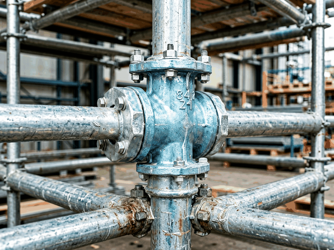
Pressed steel swivel couplers are critical connection components in tubular scaffolding systems, designed to join two scaffold tubes at variable angles while maintaining structural integrity under load. Unlike fixed couplers, swivel variants allow rotational movement between connected tubes, enabling the creation of diagonal bracing, irregular geometries, and non-orthogonal configurations essential for complex access structures. These components are manufactured through precision pressing of structural steel grades, forming a robust housing that grips scaffold tubes via mechanical tightening of bolts or wedges, ensuring slip resistance under dynamic and static loads typical in construction, maintenance, and industrial access applications.
The swivel coupler consists of two hinged jaw halves, each featuring a semi-circular recess matched to the outer diameter of standard scaffold tubes (typically 48.3 mm OD). These jaws are joined by a central pivot bolt or pin, allowing rotation while maintaining alignment under load. When the clamping bolts are tightened, the jaws deform elastically around the tube, creating a frictional grip that transfers axial, shear, and moment loads through the coupler body into the connected tubes. The pressed steel construction ensures uniform grain flow and minimal stress concentrations, critical for maintaining fatigue resistance under repeated load cycles common in erecting and dismantling operations.
Load testing reveals that properly installed pressed steel swivel couplers typically sustain safe working loads of 2.2 kN in shear and 1.5 kN in tension per coupling point, depending on tube grade and bolt torque. The swivel mechanism itself does not reduce load capacity when locked; rather, it introduces a rotational degree of freedom that must be restrained by bracing in the overall scaffold geometry. Engineers must account for potential moment accumulation at swivel joints in lateral load analyses, particularly in tall or exposed structures where wind loads induce torsional forces.
These couplers are produced from hot-rolled structural steel sheets, commonly grades S235JR or S275JR per EN 10025-2, selected for their balance of yield strength, ductility, and weldability. The pressing operation forms the coupler body in a single stroke, minimizing material waste and ensuring consistent wall thickness across critical load-bearing zones. Post-forming, components undergo deburring and surface treatment—typically hot-dip galvanizing to a minimum coating thickness of 55 μm per EN ISO 1461—to provide corrosion resistance in outdoor and humid environments, extending service life beyond five years under normal site conditions.
Manufacturing tolerances are tightly controlled: jaw alignment must maintain concentricity within 0.5 mm to ensure even tube contact, and pivot bolt holes are held to ±0.1 mm positional accuracy to prevent binding or excessive play in the swivel axis. Each batch undergoes dimensional sampling and mechanical verification, including proof load testing at 1.5 times the rated capacity, to confirm elastic behavior and permanent set limits. Traceability is maintained via batch codes stamped into the coupler body, linking each component to material certificates and process records.
The primary functional advantage of swivel couplers lies in their ability to connect tubes at any angle between 0° and 360°, enabling the construction of knee braces, tie-backs, and facial slopes that cannot be achieved with fixed or right-angle couplers alone. This flexibility is particularly valuable when scaffolding must adapt to uneven ground, curved building façades, or obstructions such as pipework and ductwork. By allowing precise angular adjustment, swivel couplers reduce the need for tube cutting or custom fabrication, lowering labor time and material waste during erection.
In shoring and falsework applications, swivel couplers facilitate the creation of inclined support systems for slabs and beams, where load paths must follow non-vertical trajectories. They are also indispensable in suspended scaffolding and cantilever systems, where diagonal bracing angles are dictated by anchor points and overcoming loads. The swivel function does not compromise rigidity when locked; instead, it enables engineers to optimize bracing geometry for stiffness and load distribution, directly influencing the overall stability factor of the scaffold structure.
| Coupler Type | Adjustable Angle | Typical Use Case | Limitation |
|---|---|---|---|
| Pressed Steel Swivel | 0°–360° | Diagonal bracing, irregular geometries, tied scaffolds | Requires proper bracing to resist moments |
| Right-Angle Coupler | Fixed 90° | Vertical/horizontal connections, ledgers, transoms | Cannot accommodate non-orthogonal joints |
| Putlog Coupler | Fixed, typically 90° | Putlogs into brickwork, light duty support | Lower load capacity, limited to specific applications |
| Sleeve Coupler | 0° (axial only) | Tube extension, longitudinal joins | No angular flexibility; resists only tension/compression |
Correct installation is critical to achieving the coupler’s rated performance. The scaffold tubes must be inserted fully into the jaw recesses until they contact the internal stop, ensuring maximum bearing surface. Clamping bolts—typically M12 or M14 grade 8.8—should be tightened to a torque range of 50–70 Nm, depending on bolt size and lubrication condition. Under-torquing risks slip under load, while over-torquing can cause thread stripping or excessive jaw deformation, both compromising safety. Torque should be checked periodically during long-term use, especially after load cycling or environmental exposure.
The swivel pivot should move freely when unloaded but exhibit no axial play when clamped. Any binding, roughness, or looseness in the pivot mechanism indicates wear, corrosion, or incorrect assembly and warrants removal from service. Lubrication of the pivot point with a light grease is permissible and may improve longevity, but must not migrate to the clamping surfaces, as this reduces frictional grip. All installation procedures should align with local scaffolding regulations, such as BS EN 12810-1 or OSHA 1926 Subpart L, which mandate competent person verification before use.
Quality control begins with incoming material verification, including mill test certificates for steel grade and mechanical properties. During production, each coupler is inspected for dimensional conformity using go/no-go gauges for jaw width, tube recess diameter, and pivot hole alignment. Surface coating is tested for thickness and adhesion via magnetic induction and cross-hatch tape tests, ensuring compliance with corrosion protection standards. Functional validation includes torque-slip testing on sample units, where the resistance to tube rotation under applied load is measured to confirm adequate clamping force.
Final inspection includes a visual check for defects such as cracks, incomplete forming, or foreign material inclusion. Couplers are also subjected to a proof load of 1.5 times the rated working load in both shear and tension directions; no permanent deformation or slip should occur. Records of all inspections are retained for traceability, and any batch failing to meet criteria is quarantined and investigated. This systematic approach ensures that only components meeting defined safety and performance thresholds are released for use in load-bearing scaffold systems.
Pressed steel swivel couplers are extensively used in petrochemical plant maintenance, where scaffolding must navigate complex pipe racks, vessels, and structural steel at varying elevations and angles. The ability to create precise diagonal bracing at non-standard angles allows safe access to nozzles, manholes, and insulated surfaces without compromising structural stability. In shipbuilding and repair, they enable the construction of suspended and hanging scaffolds that conform to hull curvatures, providing stable platforms for blasting, painting, and welding operations where fixed-angle couplers would require extensive tube modification.
In civil engineering, these couplers support falsework for curved concrete structures such as tunnels, arches, and viaducts, where formwork must follow compound geometries. They are also critical in shoring systems for deep excavations, where inclined struts and walers must connect at variable angles to resist lateral earth pressures. Even in temporary event structures—such as staging, grandstands, and exhibition halls—swivel couplers allow architects and engineers to realize non-rectangular designs while maintaining compliance with temporary structure safety codes.





