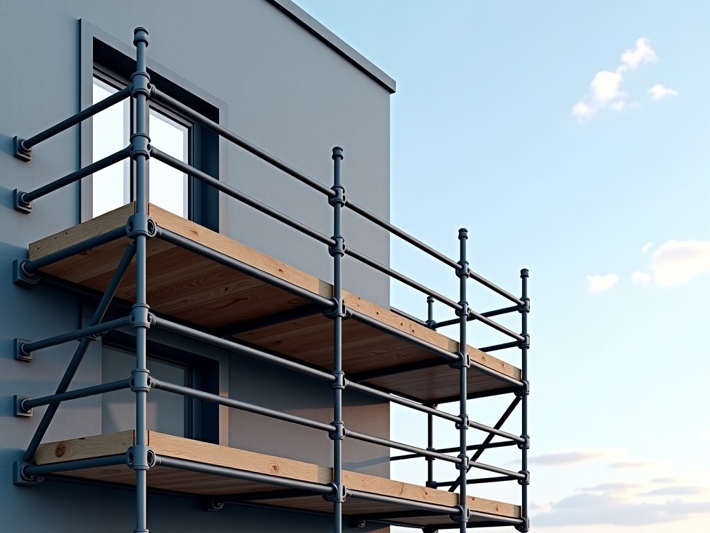
Post head jack scaffolding systems are height-adjustable support components used in formwork and falsework applications to transfer vertical loads from slab or beam forms to the ground or shoring towers. They consist of a threaded steel rod (jack), a base plate for load distribution, a nut for adjustment, and a forged or pressed steel head that engages with the formwork bearer or primary beam. The primary function is to provide precise, repeatable elevation control under sustained construction loads, typically ranging from 20 kN to 50 kN per jack depending on design and configuration.
Unlike fixed-height props or screw jacks used in shoring, post head jacks are specifically engineered for integration with timber, steel, or aluminum formwork bearers where lateral restraint and positive engagement are required. The head geometry prevents slippage during concrete pour vibration and allows for quick release after form stripping. Adjustment is manual via a handwheel or spanner nut, enabling millimeter-level height correction to compensate for ground settlement, formwork deflection, or specified camber in elevated slabs.
Material selection directly impacts durability, corrosion resistance, and load capacity. The threaded rod and adjusting nut are typically manufactured from cold-drawn steel bar (e.g., C1045 or equivalent) with tensile strength ≥ 500 MPa, induction-hardened at the thread roots to resist galling and wear. Base plates are forged from structural steel (e.g., S275JR) with a minimum thickness of 8–12 mm to prevent punching shear into soft ground or blinding layers. Head components are drop-forged from alloy steel to withstand impact and cyclic loading during formwork erection and stripping cycles.
Surface treatment is selected based on environmental exposure and project duration. Hot-dip galvanizing (HDG) per ISO 1461 provides a zinc coating of 55–85 µm, offering 5–15 years of protection in rural to moderately industrial atmospheres. For short-term indoor use or dry climates, electrogalvanizing or powder coating may be specified. In coastal or high-chloride environments, duplex systems (HDG + epoxy) or stainless steel (Grade 304/316) variants are available upon request, though at increased cost and lead time.
Adjustment range is a critical specification defined by the threaded rod length and nut travel. Standard post head jacks offer 300–600 mm of vertical adjustment, with threaded diameters of 26 mm, 32 mm, or 38 mm influencing both load capacity and rotational effort. A 32 mm diameter rod with Acme or trapezoidal thread typically requires 8–12 Nm of torque per kN of load applied, allowing manual adjustment under full design load using a standard spanner. Finer thread pitches increase resolution but reduce maximum load capacity due to reduced shear area.
Load capacity is not solely a function of material strength but also depends on end restraint, buckling length, and base plate interaction. The effective length of the jack is measured from the bearing surface of the head to the contact point of the base plate on the ground or sleeper. When used with adequate lateral bracing (e.g., connected to formwork bearers or tied to shoring frames), the jack behaves as a axially loaded column with effective length factor (K) ≈ 0.7–1.0. Without lateral support, buckling governs capacity, reducing safe working load by 40–60% compared to short, fully restrained conditions.
Base plate size and stiffness are often underestimated in temporary works design. A 150 mm × 150 mm plate distributing a 30 kN load over soil with a bearing capacity of 100 kPa requires only 20 cm² of area—well within limits—but on compacted gravel or crushed stone, punching shear through the plate thickness becomes the limit state. For this reason, base plates are frequently stiffened with gussets or manufactured with a flange thickness ≥ 10 mm to prevent deformation that could lead to uneven load transfer or jack tilting.
Thread protection and contamination control significantly affect service life and adjustment torque consistency. Exposed threads accumulate concrete slurry, dust, and debris, increasing friction and risk of thread damage during rotation. Many systems include a removable thread protector cap or a grease nipple for periodic lubrication. In high-cycle applications, specifying a lubricant with molybdenum disulfide (MoS₂) additives reduces friction by 30–50% compared to dry steel-on-steel contact, minimizing wear and ensuring consistent adjustment effort over thousands of cycles.
Compatibility with formwork bearers is determined by head geometry and bore size. Standard heads feature a U-shaped or saddle-type recess to cradle square or rectangular bearers (typically 80–100 mm width) with a vertical stop to prevent lateral displacement. Alternative heads include domed caps for steel tubes, claw-type grips for timber beams, or flat plates with bolt holes for connecting to aluminum formwork rails. The head must provide sufficient vertical guidance (minimum 25 mm engagement depth) to resist overturning moments caused by eccentric loading or wind during erection.
Quality control focuses on dimensional accuracy of threads, straightness of the rod, and forge quality of heads and bases. Thread pitch diameter is checked via go/no-go gauges per ISO 965-1, with tolerance typically held to 6g/6H class. Rod straightness is limited to 0.5 mm per 300 mm length to prevent binding during adjustment. Forged components undergo magnetic particle inspection (MPI) or dye penetrant testing (DPT) on critical load paths to detect surface cracks or laps that could propagate under cyclic load. Proof load testing at 1.5× working load limit (WLL) is standard for batch validation.
Typical applications include elevated slab formwork for commercial buildings, bridge deck soffits, parking structures, and industrial floors where precise soffit elevation is required. Post head jacks are preferred over adjustable steel props in these scenarios because they provide positive lateral restraint to the bearer, reducing the need for separate bracing or tying systems. In tunneling or shaft construction, they support temporary work platforms and concrete lining forms where access is constrained and adjustment must be performed from one side.
In residential construction, post head jacks are less common due to lower repetition and simpler formwork layouts, but they are still used in basement slabs, raft foundations, and podium decks where differential settlement must be accommodated. Their adjustability allows contractors to correct for uneven excavation or blinding layer compression without dismantling and reshoring entire sections. For post-tensioned slabs, they enable precise camber adjustment to counteract expected deflection during tensioning.
| Parameter | Typical Range / Value | Notes |
|---|---|---|
| Thread Diameter | 26 mm, 32 mm, 38 mm | Larger diameters increase capacity and reduce rotation effort per kN |
| Adjustment Range | 300–600 mm | Defined by threaded length; custom lengths available |
| Safe Working Load (SWL) | 20–50 kN per jack | Dependent on buckling length, end restraint, and material grade |
| Thread Type | Acme, Trapezoidal (Tr), or Metric ISO | Trapezoidal offers balance of strength and efficiency for manual adjustment |
| Base Plate Size | 120×120 mm to 180×180 mm | Thickness typically 8–12 mm; stiffened options available |
| Surface Finish | Hot-dip galvanized (standard), Electrogalvanized, Powder coated, SS 304/316 | HDG minimum 55 µm zinc coating per ISO 1461 |
| Head Engagement Depth | Minimum 25 mm | Required to prevent lateral slip of bearer under vibration |
Customization options are frequently requested to match project-specific formwork systems or shoring configurations. Thread length can be extended beyond standard ranges for deep soffits or adjustable height towers, though this requires buckling analysis to ensure the effective length does not compromise stability. Head geometry can be modified to accommodate non-standard bearer dimensions (e.g., wide-flange steel beams, proprietary aluminum rails) or to integrate with locking pins, wedges, or wedge clamps for rapid assembly. Base plates may be supplied with pre-drilled anchors for attachment to concrete blinding or steel grillage, or with spherical washers to accommodate slight ground slope.
Packaging and handling considerations affect site logistics and component longevity. Post head jacks are typically bundled in quantities of 25–50 units per pallet, secured with steel straps and protected by corner guards to prevent thread damage during transit. Each bundle includes a packing list with heat number, batch ID, and inspection certificate reference. For export shipments, desiccant packs and vapor corrosion inhibitors (VCI) are added to the packaging to mitigate moisture ingress during sea transit. Units are never packaged loose in bulk containers due to the risk of thread nicking and contamination from abrasive contact.
Inspection upon receipt should verify thread integrity, coating continuity, and dimensional conformity. A simple gauge check of the threaded rod using a thread ring gauge confirms pitch diameter and helix accuracy. Visual inspection of the head and base for cracks, excessive wear, or deformation is recommended before first use. Coating thickness can be spot-checked with a magnetic pull-off gauge; readings below 40 µm for HDG indicate potential undersupply and warrant supplier notification. Any unit with bent rods, stripped threads, or missing components should be quarantined and returned to the supplier.
Lead time for standard hot-dip galvanized post head jacks is typically 3–4 weeks from order confirmation, assuming raw material availability. Custom head geometries, stainless steel variants, or non-standard thread lengths extend lead time to 6–8 weeks due to tooling, forging die adjustments, and additional passivation steps. Expedited production is possible for critical path items but may incur premium charges and requires confirmation of manufacturing capacity.
To request a quotation or discuss technical specifications for your project, please provide the required load capacity, adjustment range, head geometry details, base plate size, and any environmental or material constraints (e.g., galvanizing requirement, stainless steel preference). Including a sketch or reference to your formwork bearer dimensions ensures accurate matching of the jack head interface. Our technical team will review the inputs and return a detailed response with load tables, dimensional drawings, and delivery terms.
Submit Inquiry




