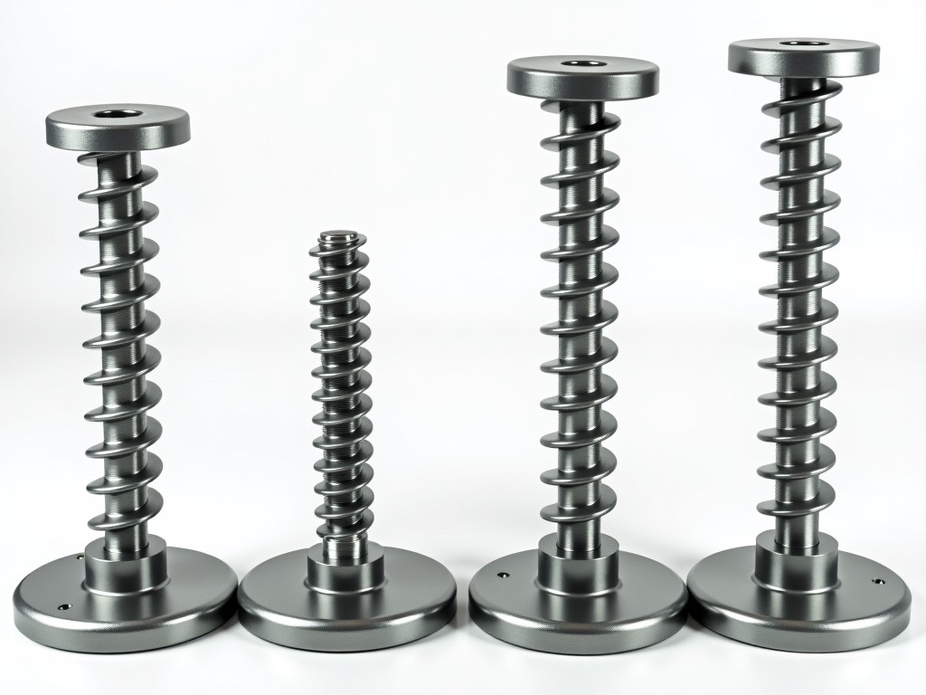
A pipe screw jack base is a foundational component in modular scaffolding systems, designed to transfer vertical loads from the scaffold structure to the supporting surface while allowing precise height adjustment. Unlike fixed base plates, screw jacks incorporate a threaded spindle mechanism that enables fine-tuned elevation control, critical for establishing level working platforms on uneven or sloped substrates.
The primary function of this component is load distribution and stability enhancement. By converting rotational input into linear displacement via Acme or trapezoidal threads, the screw jack allows installers to compensate for ground irregularities without shimming or cutting scaffold tubes. This adjustment capability directly impacts scaffold safety, as even minor deviations from plumb can amplify into significant lateral forces at height.
In temporary works engineering, the screw jack base serves as the interface between the scaffold’s vertical standards and the foundation. Proper selection and installation influence the system’s resistance to settlement, lateral drift, and overturning moments—particularly important in high-rise scaffolding, suspended access systems, or heavy-duty shoring applications where dynamic loads and environmental factors are present.
Pipe screw jack bases are engineered to interface with standard scaffold tube diameters, most commonly 48.3 mm OD (1.5-inch NPS) steel pipe, though adaptations exist for 42.4 mm and 60.3 mm variants. The spindle is typically manufactured from cold-drawn steel with a tensile strength of ≥450 MPa, featuring rolled threads to improve fatigue resistance and surface hardness compared to cut threads.
The base plate distributes the applied load over a sufficient area to prevent localized sinking into soft soils or damage to finished surfaces. Standard base plates range from 150 mm × 150 mm to 200 mm × 200 mm square, with thicknesses between 6 mm and 10 mm depending on load class. Some designs include lugs or holes for anchoring to substrates or securing sole plates.
Adjustment range varies by model, typically spanning 250 mm to 600 mm of usable thread length. This corresponds to a vertical adjustment capacity that allows compensation for slopes up to 1:10 (approximately 5.7 degrees) without requiring additional shimming. The threaded interface incorporates a stopping mechanism—often a collar or nut—to prevent over-extension and maintain engagement safety.
Load ratings for pipe screw jack bases are determined through static testing in accordance with regional standards such as EN 12811-1 (Europe), ANSI/SSFI SC-100-5/05 (North America), or AS/NZS 1576 (Australasia). These ratings reflect the maximum permissible working load under concentric axial compression, assuming proper installation and full thread engagement.
Typical working load limits range from 20 kN to 36 kN (approximately 4,500 lbf to 8,000 lbf) per jack, depending on spindle diameter, base plate size, and material grade. Higher-capacity variants, often used in shoring or falsework, may exceed 50 kN. It is essential to note that these values assume vertical loading; any eccentricity or lateral force reduces effective capacity and must be evaluated per scaffold design calculations.
The screw mechanism itself contributes to system stiffness. A finer thread pitch (e.g., 5 mm) provides greater resolution but requires more rotations for adjustment, while a coarser pitch (e.g., 6 mm or 7 mm) allows faster height changes at the expense of precision. Most scaffolding jacks use a 6 mm pitch as a balance between usability and control, compatible with standard adjustable spanners or socket wrenches.
The spindle and adjusting nut are predominantly made from carbon steel (e.g., C45 or equivalent) due to its strength, machinability, and cost-effectiveness. For environments with elevated corrosion risk—such as coastal areas, chemical plants, or prolonged outdoor exposure—alternatives include hot-dip galvanized steel, stainless steel (grades 304 or 316), or zinc-nickel plated finishes.
Base plates are typically fabricated from structural steel plate (e.g., S235JR or A36) and receive the same protective coating as the spindle to ensure uniform corrosion resistance. Hot-dip galvanizing per EN ISO 1461 or ASTM A123 is common, providing a zinc coating thickness of 55–85 µm, which offers 15–25 years of protection in rural to mildly industrial atmospheres.
In applications where painting is preferred or required (e.g., to match site-specific color codes), epoxy primers followed by polyurethane topcoats are used. However, coated finishes demand regular inspection for damage, as localized coating failure can accelerate underfilm corrosion. Galvanized finishes are generally favored for rental equipment due to their durability and low maintenance.
Pipe screw jack bases are ubiquitous in supported scaffolding systems where vertical standards must bear weight. Their adjustability makes them indispensable in facade refurbishment, where building exteriors often exhibit deviations from plumb due to settlement, thermal movement, or construction tolerances. Without this compensation, scaffold tubes would bind or induce tripping hazards at board level.
In shoring and falsework for concrete construction, screw jacks support formwork beams and decking under wet concrete loads, which can exceed 15 kPa. Here, the ability to make incremental adjustments during pour sequencing helps mitigate differential settlement and maintain soffit tolerances. The jack’s load-holding capability under sustained pressure is critical, as creep in the thread interface must be minimized over hours or days.
Industrial maintenance scaffolding in refineries, power plants, and mills frequently employs screw jacks on uneven grating, trench covers, or damaged flooring. The corrosion-resistant variants are selected here to withstand chemical splash, humidity, and temperature cycling. Additionally, in suspended scaffold systems, screw jacks may anchor outriggers or counterweight frames to rooftops or structural edges, where precise leveling prevents wire rope slack or overload.
Fixed base plates, while simpler and less expensive, offer no height adjustment and rely entirely on shimming or substrate preparation to achieve level. This approach increases labor time and introduces variables such as shingle compression or settling of granular fill. In contrast, screw jacks consolidate adjustment into a single, repeatable mechanism, reducing dependency on site conditions.
Swivel bases combine a screw jack with a hinged or ball-jointed base plate, allowing angular compensation in addition to vertical adjustment. These are advantageous on sloped surfaces or where the scaffold leg must meet the foundation at an angle. However, swivel mechanisms add complexity, potential wear points, and slightly higher cost, making them less common in standard facade scaffolding where near-vertical loading predominates.
Threaded inserts or nut plates embedded in concrete offer a permanent adjustment point but are impractical for temporary works due to installation lead time and lack of reusability. Screw jacks retain the advantage of portability and rapid deployment, essential for rental scaffolds that undergo frequent assembly and disassembly cycles across multiple projects.
Manufacturing consistency is verified through dimensional inspection of critical features: spindle straightness (typically <0.5 mm/m runout), thread pitch accuracy (±0.1 mm), and base plate flatness (<0.3 mm deviation across surface). These parameters ensure smooth operation and even load distribution, preventing binding or localized stress concentrations in the threaded interface.
Mechanical properties are validated via spot testing of raw material and finished components. Tensile strength, yield strength, and elongation are assessed to confirm compliance with specified grades. For threaded components, proof load testing ensures the spindle can withstand forces exceeding the rated working load without permanent deformation—typically to 150% of rated capacity for a minimum of 3 minutes.
Corrosion protection quality is measured by coating thickness (using magnetic or eddy current gauges) and adhesion testing (per ASTM D4541 or ISO 4624). Salt spray testing (ASTM B117) may be conducted on sample batches to verify coating durability, with acceptable results showing <5% red rust after 500 hours for hot-dip galvanized finishes. These checks are particularly important for rental fleets subjected to repeated environmental exposure.
While standard configurations suit most scaffolding applications, certain projects require tailored solutions. Spindle length can be adjusted to accommodate non-standard adjustment ranges—either extended for deep foundations or shortened for confined spaces where overhead clearance is limited. Thread form may also be modified; for example, Acme threads are sometimes specified for high-cycle applications due to their improved wear characteristics compared to standard metric threads.
Base plate geometry is adaptable to substrate conditions. Larger plates (e.g., 250 mm × 250 mm) reduce ground pressure for use on soft soils, asphalt, or fragile finishes like waterproofing membranes. Conversely, smaller or contoured plates may be designed to fit around protrusions, drainage grates, or structural anchors. Slotted or perforated bases allow drainage or enable anchoring via stakes or bolts.
Surface treatments can be specified beyond standard galvanizing. Powder coating offers UV resistance and color consistency for architectural projects where scaffolding remains visible for extended periods. In hygienic or cleanroom environments, electropolished stainless steel finishes minimize particle retention and facilitate cleaning. Thread lubricants or anti-seize compounds may be pre-applied to prevent galling during repeated adjustment cycles.
Proper installation begins with verifying that the screw jack is oriented correctly—the spindle must be vertical, and the base plate must sit flat on the supporting surface. If the substrate is uneven, the jack should be adjusted to compensate before attaching the scaffold standard. Forcing a standard into a misaligned jack can damage threads or create dangerous eccentric loading.
Engagement depth is critical for safety. The adjusting nut must maintain a minimum of 1.5 times the spindle diameter in thread engagement with the base plate or standard tube. Most designs include a visual indicator—such as a holeslot or painted band—to show when maximum safe extension is approached. Exceeding this limit risks thread stripping or nut disengagement under load.
Load should be applied concentrically through the center of the spindle. Lateral forces, such as those from leaning equipment or uncontrolled access, must be mitigated via bracing or tying back to the structure. Regular inspection during use is recommended: check for bent spindles, cracked nuts, deformed base plates, or excessive thread wear. Lubrication of the threads with a suitable grease reduces operating torque and prevents corrosion-induced seizing.
Routine maintenance focuses on preserving thread integrity and corrosion protection. After each use, spindles should be cleaned of dirt, concrete splatter, or debris that could abrasive wear the threads during adjustment. A light application of water-resistant grease (e.g., lithium-based or molybdenum disulfide) helps prevent galling and ensures smooth operation over thousands of cycles.
Periodic inspections should assess: straightness of the spindle (visual or with straightedge), thread condition (no galling, pitting, or deformation), base plate flatness and thickness (no bending or corrosion-induced thinning), and nut rotation (smooth without binding). Any component showing cracks, permanent distortion, or excessive wear must be removed from service immediately.
For rental equipment, inspection intervals are often tied to usage cycles—typically every 10–20 uses or quarterly, whichever comes first. Documentation of checks supports traceability and compliance with local regulations. In aggressive environments, ultrasonic testing or magnetic particle inspection may be employed to detect subsurface flaws not visible externally.
When requesting a quotation or placing an order, specifying the following details ensures accurate fulfillment: scaffold tube diameter (OD), required adjustment range, base plate dimensions and thickness, material grade (e.g., carbon steel, galvanized, stainless), and any special features such as lugs, holes, or custom coatings. For replacement parts, providing the existing part number or a clear photograph aids in matching compatibility.
Lead times vary based on material availability and complexity. Standard carbon steel jacks with galvanized finish typically ship within 2–4 weeks for orders under 500 units. Custom materials (e.g., stainless steel) or non-standard dimensions may extend lead time to 6–8 weeks. Expedited production is possible for critical projects but may incur additional charges.
Packaging is designed to protect finishes and prevent deformation during transit. Spindles are often bundled in protective wrapping or placed in dividers within palletized crates. Base plates are stacked with separators to avoid surface scratching. For export shipments, moisture-barrier packaging and corner reinforcement are standard to withstand handling and climate variations.
Minimum order quantities apply to customized items, while standard configurations are often available from stock or in small batch runs. Sampling is supported for validation purposes—typically 1–5 units can be supplied for trial or testing, with costs credited toward a subsequent bulk order. All products are supplied with material traceability and conformity documentation upon request.
| Parameter | Typical Range | Notes |
|---|---|---|
| Spindle Diameter | 20 mm – 32 mm | Affects load capacity and thread strength |
| Thread Pitch | 5 mm – 7 mm | 6 mm is most common for balance of speed and control |
| Adjustment Range | 250 mm – 600 mm | Usable thread length; excludes safety stop |
| Base Plate Size | 150×150 mm – 200×200 mm | Larger sizes available for soft ground |
| Base Plate Thickness | 6 mm – 10 mm | Influences bending resistance |
| Working Load Limit | 20 kN – 36 kN | Per jack; concentric load only |
| Coating Thickness (Galvanized) | 55 µm – 85 µm | Per EN ISO 1461 or ASTM A123 |
| Material (Spindle) | C45 / 1.0503 equivalent | Cold-drawn, tensile strength ≥450 MPa |





