Scaffolding systems are temporary structures designed to support workers, materials, and equipment during construction, maintenance, and repair operations. Their safety and functionality depend entirely on the precise interaction of individual components, each engineered to specific load-bearing, dimensional, and connection requirements. Understanding the function and specification of each part is essential for proper system selection, assembly, and compliance with regional safety standards such as OSHA, EN 12810/12811, or AS/NZS 1576.
This page details the core components of a modular scaffolding system, explaining their mechanical roles, material considerations, and compatibility factors. Information is presented to assist engineers and procurement specialists in evaluating system integrity, planning replacements, or specifying new installations based on project demands rather than promotional claims.
The vertical and horizontal load-bearing elements form the backbone of any scaffolding system. Standards define their geometry, material thickness, and connection interface to ensure predictable performance under combined dead and live loads. These parts are typically fabricated from hot-rolled or cold-formed steel with standardized tube diameters and wall thicknesses to maintain interchangeability across manufacturers within the same system type.
Vertical standards (also called uprights or posts) transfer loads from the working platform down to the foundation or base plates. Their spacing directly influences the system’s load capacity and is determined by the intended use—light duty for painting or inspection, medium duty for general construction, or heavy duty for masonry or concrete work. Horizontal ledgers and transoms connect between standards to create bays and support decking; ledgers run parallel to the building facade, while transoms span perpendicularly to carry planks or panels.
Diagonal and planar bracing prevent lateral sway and rotational instability, especially under wind loads or eccentric loading from equipment and personnel. Without adequate bracing, even vertically strong standards can buckle or collapse due to insufficient moment resistance. Bracing geometry follows triangulation principles to convert lateral forces into axial loads within the members, which steel resists more effectively than bending or shear.
Facade bracing runs diagonally along the outer face of the scaffold, tied to the building structure at intervals to resist wind-induced oscillation. Plan bracing, installed horizontally at base, mid, and top levels, prevents racking within the scaffold plane. Swivel couplers or fixed connectors are used to attach bracing tubes to standards and ledgers, with angle adjustability accommodating irregular building facades or non-90° corners.
The working platform must provide a safe, slip-resistant surface capable of supporting personnel, tools, and materials without excessive deflection. Decking materials are selected based on load requirements, durability, and ease of installation. Deflection limits are typically governed by safety codes—often L/180 or L/240 of the span—to prevent tripping hazards and ensure worker confidence.
Common decking options include steel planks with perforated or serrated surfaces for drainage and grip, aluminum planks for lighter weight and corrosion resistance, and laminated wood or composite boards where non-conductivity is required. Steel planks often feature hooks or lugs that engage with ledger transoms to prevent uplift or lateral displacement. Overlapping or interlocking designs minimize gaps between planks, reducing fall-through risks.
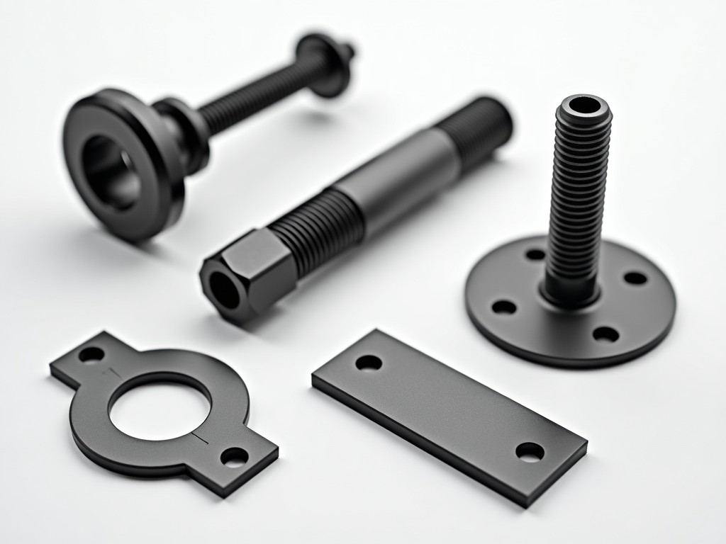
Load transfer from the scaffold to the ground or structure begins at the base. Base plates distribute concentrated loads from standards over a larger area to prevent sinking into soft soil or damaging finished surfaces. Adjustable base plates incorporate threaded spindles to compensate for uneven terrain, allowing precise vertical alignment of the scaffold without shimming or temporary grading.
In applications requiring higher load dispersion—such as on soft ground, asphalt, or suspended slabs—timber sole plates or steel spreader beams are placed beneath base plates to further reduce ground pressure. Anchor ties, when used to secure the scaffold to a building structure, connect to standards via scaffold eyes or through-bolts and must be designed to resist both tensile and shear forces as per engineering calculations.
The integrity of a scaffolding system relies on its ability to securely join components while allowing rapid assembly and disassembly. Couplers must maintain specified slip and crush resistance under cyclic loading, as verified through standardized testing procedures. Material consistency, thread engagement, and tightening torque are critical factors in preventing joint failure over time.
Right-angle couplers (also called swivel or fixed couplers depending on type) connect tubes at 90° angles for ledger-to-standard or transom-to-standard joints. Swivel couplers allow variable angles for bracing applications. Putlog couplers, with a narrower throat, are designed to bear on building structures or putlogs rather than tube-to-tube connections. All couplers are typically drop-forged or investment-cast steel with galvanized finishes to resist corrosion and ensure consistent dimensional tolerances.
Safe access to working platforms and fall protection are integral to scaffolding design, not optional additions. Ladders, stair towers, and gate systems must meet specific dimensional and load requirements to ensure safe ingress and egress under routine and emergency conditions. Guardrails and toe boards prevent falls and tool drop hazards, with heights and gap sizes regulated by jurisdictional standards.
Access ladders are typically vertical or inclined, with rung spacing not exceeding 30 cm and a minimum width of 30 cm. Stair tower systems provide easier access for frequent movement of personnel or materials, featuring treads, handrails, and intermediate landings. Double guardrail systems—consisting of a top rail at 950–1150 mm and a mid-rail—along with toe boards at least 150 mm high, are standard on all open sides and ends of working platforms above 2 meters in height.
Interchangeability between components from different manufacturers depends on adherence to defined system specifications—tube diameter, wall thickness, coupling type, and spacing dimensions. Deviations, even minor ones, can compromise joint strength or lead to premature wear. Common tube outer diameters include 48.3 mm (1.5 inches) and 42.4 mm, with wall thicknesses ranging from 2.7 mm to 4.0 mm depending on duty rating.
Material selection affects durability, weight, and environmental resistance. Hot-dip galvanized steel is standard for most components due to its balance of strength, cost, and corrosion protection. Aluminum alloys are used in specialized applications where weight reduction or non-sparking properties are prioritized. Stainless steel may be specified in corrosive environments such as chemical plants or marine settings, though its higher cost limits widespread use.
Reliability in scaffolding components stems from consistent manufacturing processes and rigorous inspection protocols. Dimensional accuracy, material thickness, weld integrity (where applicable), and coating adhesion are verified at multiple stages. Non-conforming parts are segregated to prevent accidental use in assembled structures.
Inspection typically includes tube straightness checks, coupler drop-test simulations, thread gauge verification for adjustable bases, and visual assessment for cracks, bends, or excessive corrosion. Mill test certificates for raw materials and batch-specific test reports for critical components like couplers are available upon request. Periodic re-inspection of in-service equipment is recommended to detect deformation, wear, or damage from prior use.
| Component Category | Typical Material | Key Dimensional Parameters | Primary Function |
|---|---|---|---|
| Vertical Standards | Hot-rolled steel, galvanized | 48.3 mm OD, 2.7–4.0 mm wall | Transfer axial loads to foundation |
| Horizontal Ledgers | Hot-rolled steel, galvanized | 48.3 mm OD, 2.7–3.2 mm wall | Connect standards, support transoms |
| Facade Braces | Hot-rolled steel, galvanized | 48.3 mm OD, 2.7–3.2 mm wall | Resist lateral and wind loads |
| Base Plates | Forged or pressed steel, galvanized | 150x150 mm or 200x200 mm plate | Distribute load to ground or structure |
| Right-Angle Couplers | Drop-forged steel, galvanized | Fits 48.3 mm tube, 19 mm bolt | Secure 90° tube connections |
| Steel Planks | Cold-formed steel, galvanized | 225–300 mm width, 1.2–1.5 mm thick | Provide working platform surface |
| Guardrail Posts | Hot-rolled steel, galvanized | 48.3 mm OD, 2.7–3.2 mm wall | Support top and mid-rails |
| Adjustable Base Spindles | Forged steel, galvanized | 30–36 mm diameter, 250–500 mm travel | Compensate for uneven foundations |
Each component in a scaffolding system plays a defined role in maintaining structural stability, load capacity, and worker safety. Specifying parts based on engineering requirements—rather than assuming interchangeability—reduces risk of assembly errors, non-compliance, or premature failure. For technical data sheets, material certifications, or compatibility guidance on specific system types, contact our engineering team to discuss your project’s access and support requirements.





