Parts of Metal Scaffolding in Construction
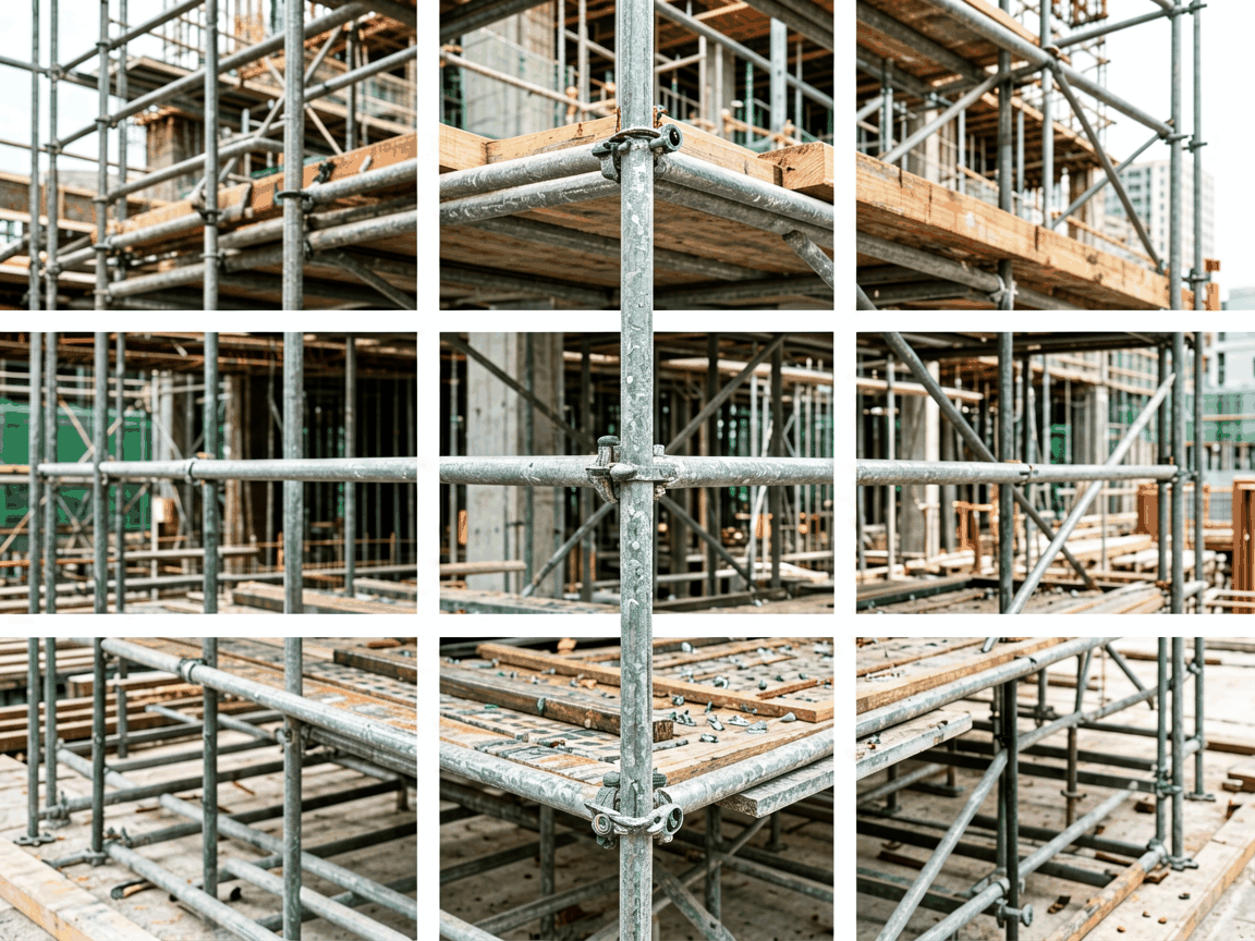
Metal scaffolding systems are engineered temporary structures used to support workers, materials, and equipment during construction, maintenance, and repair activities. Their performance depends on the precise function and interaction of individual components, each designed to meet specific load, stability, and safety requirements. Understanding the role of each part is essential for proper assembly, inspection, and risk mitigation on site.
Primary Load-Bearing Components
The vertical and horizontal members form the backbone of any scaffolding system, transferring loads from the working platform to the ground or supporting structure. These components must resist buckling, bending, and shear forces under dynamic and static conditions, with design governed by standards such as EN 12810/12811 or OSHA 1926 Subpart L.
- Standards (vertical tubes): Typically 48.3mm OD steel tubes with a wall thickness of 3.2mm or 4.0mm, spaced at 1.5m to 2.0m intervals depending on load class. They feature collar lugs or rosettes at 500mm or 600mm intervals for horizontal connection.
- Ledgers (horizontal tubes): Connect between standards to define bay width and support transoms. Common lengths range from 0.6m to 3.0m, with end fittings designed to lock securely into standard connectors without wobble.
- Transoms: Shorter horizontal members placed perpendicular to ledgers to support scaffold boards or decking. Typically 0.3m to 0.9m long, they prevent lateral spread and distribute point loads from materials or personnel.
Stability and Bracing Elements
Lateral stability is critical to prevent sway, twisting, or collapse under wind, eccentric loads, or accidental impact. Bracing systems transfer these forces to the ground or building structure through triangulated load paths, significantly increasing rigidity compared to vertical and horizontal members alone.
- Facade bracing: Diagonal tubes connected from the base of outer standards to higher points on the same elevation, resisting in-plane wind loads parallel to the building facade.
- Plan bracing: Installed at ground level and periodically up the height, connecting outer and inner standards in a zigzag pattern to prevent racking and twisting of the entire bay.
- Tie tubes: Adjustable steel tubes with screw jacks or wedge fittings that anchor the scaffold to the building structure at vertical intervals (typically every 4m in height and 6m horizontally), transferring wind and eccentric loads directly to the facade.
Working Platform and Access Components
The platform must provide a safe, slip-resistant working surface with adequate width and load capacity for personnel, tools, and materials. Access components ensure safe vertical movement between levels, reducing fall risks during ascent and descent.
- Scaffold boards: Typically 225mm wide, 38mm thick, and up to 3.0m long, made from seasoned spruce or pine with metal end bands to prevent splitting. They support uniformly distributed loads of 150kg/m² to 300kg/m² depending on scaffolding class.
- Toeboards: 150mm high vertical barriers fixed along the platform edge to prevent tools or materials from falling. Must withstand impact forces without displacement.
- Ladder access: Heavy-duty steel ladders with 300mm rung spacing, offset to avoid interference with platform boards, and equipped with safety gates at each level to prevent accidental falls through openings.
- Stair towers: Prefabricated stair units with 190mm rise and 250mm going, used for high-frequency access in projects requiring prolonged worker movement between levels.
Couplers and Connection Hardware
The integrity of the entire scaffold depends on the reliability of its couplers, which join tubes at fixed angles and must resist slip and tensile failure under load. These components are subject to regular inspection due to their critical role in structural continuity and their susceptibility to wear, corrosion, or deformation from repeated use.
| Coupler Type |
Function |
Typical Material |
Minimum Slip Resistance (EN 74) |
| Right-angle coupler |
Connects ledger/transom to standard at 90° |
Drop-forged steel, galvanized |
6.25 kN |
| Swivel coupler |
Connects tubes at variable angles for bracing |
Drop-forged steel, galvanized |
6.25 kN |
| Putlog coupler |
Supports transom on single standard (wall-mounted) |
Drop-forged steel, galvanized |
3.0 kN |
| Sleeve coupler |
Joins two standards end-to-end for extension |
Drop-forged steel, galvanized |
Tensile: 10.0 kN |
Base Support and Adjustment Components
Proper load transfer to the ground requires stable, level foundations, especially on uneven or soft surfaces. Base components distribute concentrated loads from standards over a wider area and allow for vertical adjustment to compensate for slope or settlement, preventing localized overstress and instability.
- Base plates: 150mm x 150mm steel plates with a central tube socket, designed to spread the load from a standard over at least 0.0225m² to prevent sinking into soft ground or damaging finished surfaces.
- Adjustable base jacks: Threaded steel spindles with a base plate and adjustable nut, allowing up to 300mm of vertical correction. Commonly used on slopes or unfinished foundations where precise leveling is required.
- Castor wheels: Lockable swivel casters with 150mm to 200mm diameter polyurethane tires, used on mobile scaffolds for short-term repositioning. Must include dual-action brakes to prevent movement when locked.
Material and Finish Considerations
The choice of material and protective coating directly affects the scaffold’s lifespan, maintenance requirements, and suitability for specific environments. Steel remains the dominant material due to its strength-to-weight ratio, durability, and recyclability, while surface treatments are selected based on exposure conditions and project duration.
- Base material: Hot-rolled structural steel (S235JR or equivalent) for tubes and forged components, offering minimum yield strength of 235 MPa and good weldability for repair or modification.
- Galvanization: Hot-dip zinc coating (minimum 55μm average thickness) provides barrier and sacrificial protection against corrosion, extending service life to 15+ years in outdoor environments with periodic inspection.
- Powder coating: Alternative finish for indoor or low-exposure applications, offering UV resistance and color coding for inventory management, though less resistant to mechanical damage than galvanizing in harsh conditions.
- Aluminum scaffolding: Used where weight reduction is critical (e.g., overhead work, fragile roofs), with 6063-T5 alloy tubes offering approximately one-third the weight of steel but requiring larger diameters to achieve equivalent stiffness.
Inspection and Maintenance Points
Regular inspection is not only a regulatory requirement but a fundamental risk control measure. Components must be checked for deformation, corrosion, wear, and proper function before each use, after modifications, and following exposure to extreme weather or impact. Defective parts must be quarantined and replaced to prevent progressive failure.
- Tube inspection: Look for dents, bends, or wall thinning (>10% reduction) that compromise buckling resistance; check couplers for cracked jaws, worn threads, or deformed locking mechanisms.
- Platform components: Examine scaffold boards for splits, rot, or metal band detachment; verify toeboards are secure and undamaged.
- Base components: Ensure base plates sit flat and jacks turn freely without binding; verify castor brakes engage and hold under load.
- Connection integrity: Confirm all couplers are fully tightened and pins/safety clips are in place; loose connections are a leading cause of scaffold accidents.
Request Technical Specifications or Quotation





