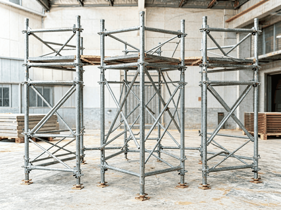
An H frame scaffolding system consists of standardized components designed to interlock securely, forming a stable vertical and horizontal framework for temporary access and support in construction, maintenance, and industrial applications. Understanding the function and specifications of each part is essential for safe assembly, load distribution, and compliance with regional safety standards such as OSHA, EN 1004, or AS/NZS 1576.
The primary load-bearing elements are the H-shaped frames, which consist of two vertical legs connected by a horizontal brace at the top and bottom, forming a rigid "H" profile. These frames are typically made from cold-formed steel tubing with outer diameters ranging from 48.3 mm to 60.3 mm and wall thicknesses between 2.0 mm and 3.2 mm, depending on load class. The vertical legs feature perforations or pin holes at 50 mm or 60 mm intervals to enable secure coupling with horizontal and diagonal bracing members.
Horizontal ledgers, also known as bearers or transoms, connect between the vertical legs of adjacent H frames to create working platforms and distribute lateral loads. These components are usually fabricated from the same steel tubing as the frames, with lengths standardized to match bay widths (e.g., 1.0 m, 1.2 m, 1.8 m, 2.4 m). End fittings include forged steel couplers or wedge locks designed to resist slip and rotation under load, with typical shear capacities exceeding 5 kN per connection when properly installed.
Diagonal braces, or sway braces, are installed between frames at alternating angles to prevent racking and enhance overall rigidity. These are typically tubular steel members with swivel or fixed end fittings that attach to the frame’s perforation points. Their effective length varies based on bay height and width, but they are commonly sized to resist buckling under compressive loads of 3–8 kN, depending on angle and end restraint. Proper bracing configuration is critical to achieving the system’s rated load capacity, which is determined through engineering analysis of the entire bay geometry.
Working platforms are supported by transoms or putlogs that span between ledgers, providing a base for decking materials such as steel planks, aluminum walkways, or laminated wood decking. Transoms are similar in construction to ledgers but are oriented perpendicular to the frame’s length and designed to carry concentrated loads from workers, tools, and materials. Typical transom spacing ranges from 300 mm to 600 mm to limit deflection under uniform loads of 2.0 kN/m² (light duty) to 3.0 kN/m² (medium duty), with end bearings designed to prevent localized crushing of the ledger tube.
Access to different levels is achieved through ladder frames, stair towers, or integrated ladder sections that attach to the H frame’s vertical legs. Ladder frames are modular units with rungs spaced at 300 mm intervals, constructed from the same tubing as standard frames but with additional reinforcement at rung-to-stringer joints. Stair systems use prefabricated steel or aluminum treads with risers of 190 mm and treads of 250 mm to comply with ergonomic and safety guidelines, and are anchored to the scaffold via bolted or clamped connections at each level.
Base plates or screw jacks are fitted to the bottom of each vertical leg to transfer loads to the ground or substructure while allowing for height adjustment and leveling. Base plates are typically 150 mm × 150 mm steel squares with a central boss to fit over the tube end, distributing pressure over a minimum area of 20,000 mm² to reduce ground bearing stress. Screw jacks incorporate a threaded spindle with a nominal diameter of 26 mm or 30 mm, adjustable over a range of 250 mm to 500 mm, and are rated for axial loads up to 25 kN when fully engaged and properly seated.
To prevent uplift or lateral movement, especially in exposed or tall configurations, tie-in systems anchor the scaffold to the building structure at regular intervals. These consist of adjustable steel ties, scaffold tubes, or proprietary anchors connected via right-angle or swivel couplers. Tie-in spacing is governed by height-to-base ratio and wind exposure, commonly placed every 4 m vertically and 6 m horizontally for medium-rise scaffolds, with each tie capable of resisting tensile and shear loads of at least 10 kN.
The integrity of the scaffolding system depends on reliable connections between components. Common locking mechanisms include pin-and-clip, wedge-lock, and threaded coupler systems. Pin-and-clip systems use a steel pin inserted through aligned holes in the frame and brace, secured by a spring clip to prevent withdrawal. Wedge-lock systems rely on a tapered wedge driven into a housing to create friction and mechanical lock, offering quick assembly and high resistance to vibration-induced loosening. Threaded couplers, while less common in H frame systems, provide adjustable tension and are used in specialized applications requiring precise alignment.
Connection strength is validated through pull-out and shear testing, with typical minimum values exceeding 15 kN for wedge-lock and pin systems when manufactured to tolerances of ±0.5 mm on hole diameter and pin size. Corrosion protection is applied via hot-dip galvanizing (minimum 55 µm zinc coating) or electroplating with chromate sealing, ensuring durability in outdoor and humid environments. Regular inspection of locking components for wear, deformation, or corrosion is required to maintain safety factors.
The structural performance of H frame scaffolding is directly tied to material selection and fabrication quality. Standard frames use hot-rolled or cold-formed steel grades such as S235JR or S355JR, chosen for their yield strength (230–355 MPa), ductility, and weldability. Tubing is formed via electric resistance welding (ERW) or seamless processes, with dimensional tolerances held to ±0.5 mm on diameter and ±10% on wall thickness to ensure consistent fit and load distribution. End fittings are forged or machined from steel bar and heat-treated to achieve surface hardness of 40–55 HRC for wear resistance.
Manufacturing processes include precision punching of perforation points, robotic welding of brackets and braces, and automated coating lines for uniform galvanization. Quality control involves dimensional checks, weld penetration testing (minimum 3 mm throat for fillet welds), and coating thickness verification using magnetic induction gauges. Batch traceability is maintained through laser etching or stamping of heat numbers and production dates on critical components, enabling recall or inspection if needed.
H frame scaffolding systems are classified according to load capacity per bay, as defined by international standards. Light duty (Class 2) systems support up to 1.5 kN/m², suitable for inspection, painting, and light maintenance. Medium duty (Class 3) handles 2.0–3.0 kN/m², appropriate for general construction, masonry, and plastering. Heavy duty (Class 4) systems, rated for 3.0–4.5 kN/m², are used for concrete formwork, stone cladding, and equipment support. The load class is determined by the weakest link in the assembly—typically the frame’s buckling resistance, coupler strength, or decking deflection—and must be verified through system-level testing or engineering calculation.
Application selection also considers height limitations, base conditions, and environmental factors. For example, a medium duty system with 2.0 m bay width and 1.8 m frame height may reach a maximum free-standing height of 9.0 m when tied in every 3 m vertically, assuming a base ratio of 1:4 and no eccentric loading. In contrast, the same system on soft soil requiring screw jacks may reduce allowable height due to settlement risk. Manufacturers provide load charts and configuration guides based on validated finite element analysis or physical testing to assist in safe specification.
Regular inspection is critical to maintaining structural integrity throughout the scaffold’s service life. Key inspection points include checking for bent or cracked tubes, worn or deformed perforations, loose or missing pins/clips, corroded sections (especially at ground level), and damaged base plates or screw jacks. Non-destructive testing such as magnetic particle inspection may be used on high-stress couplers in rental fleets. Components showing plastic deformation, cracks exceeding 1 mm, or coating loss over 20% of surface area should be removed from service and evaluated for repair or replacement.
Maintenance involves cleaning debris, lubricating threaded spindles on screw jacks, and storing components in dry, ventilated areas to prevent moisture retention. Galvanized coatings can be repaired locally using zinc-rich primers if damage is superficial. Rental and fleet operators often implement tracking systems with barcodes or RFID tags to monitor usage cycles, inspection history, and retirement thresholds—typically after 5–10 years or 500 erection cycles, depending on usage severity and environmental exposure.
For technical inquiries, configuration assistance, or quotation requests regarding H frame scaffolding components, please contact our engineering team. We provide detailed load charts, compatibility matrices, and specification support to ensure your system meets project requirements and safety standards.
Contact Our Team




