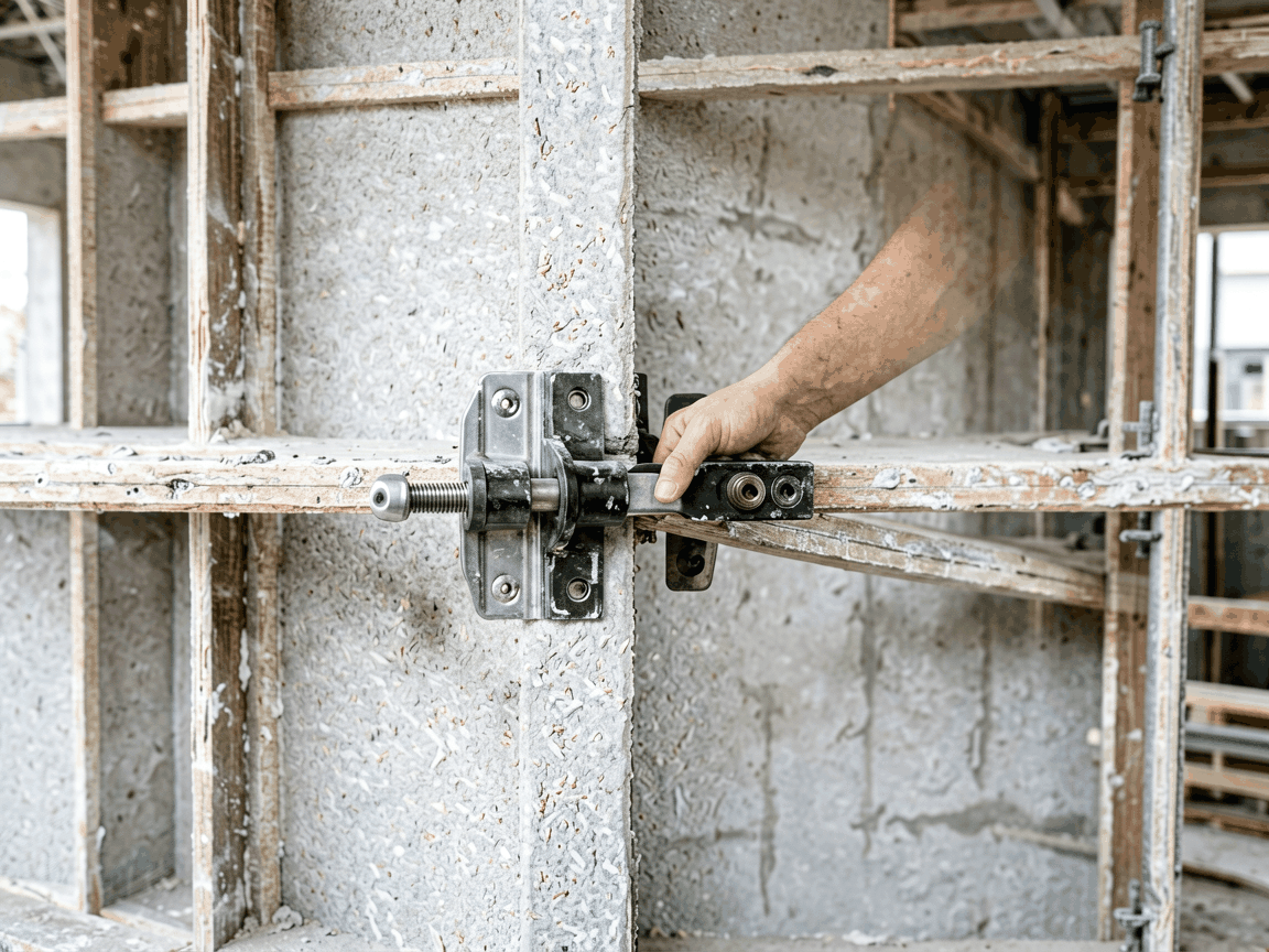
Panel bar clamps are mechanical fastening devices used to securely connect formwork panels during concrete pouring operations. They apply controlled clamping force to maintain alignment, prevent joint movement, and resist lateral pressure from wet concrete, ensuring dimensional accuracy and surface quality in cast-in-place structures.
The clamp consists of a forged steel jaw, a threaded spindle, and a handle or ratchet mechanism. When tightened, the jaw moves linearly to grip the panel’s edge or flange, generating compressive force perpendicular to the joint. The spindle design allows incremental adjustment to accommodate panel thickness variations and thermal expansion during curing.
Force distribution is optimized through a wide contact surface on the jaw, reducing localized deformation on thin-gauge steel or aluminum formwork. Most models incorporate a safety stop to prevent over-tightening, which could damage the panel or compromise the clamp’s elastic range.
Critical components are typically made from quenched and tempered alloy steel (e.g., 42CrMo4) with a tensile strength of 900–1100 MPa and yield strength exceeding 700 MPa. This ensures resistance to permanent deformation under repeated cyclic loading, common in high-rise construction where clamps may experience hundreds of load cycles.
Surface treatments include hot-dip galvanizing (minimum 60 μm zinc coating) or electrophoretic painting to resist corrosion in alkaline concrete environments. Internal spindle threads are often hardened and lubricated to maintain consistent torque output over 5,000+ cycles without galling.
Standard panel bar clamps are rated for safe working loads between 15 kN and 25 kN per clamp, depending on jaw geometry and spindle diameter. This range accommodates typical formwork pressures in walls and columns up to 4 meters high, where lateral concrete pressure can reach 40–60 kPa.
Testing follows EN 12812 or equivalent standards, involving static load application to 1.5 times the rated capacity for 10 minutes, followed by 5,000 fatigue cycles at 75% of working load. Clamps must show no cracks, permanent deformation exceeding 0.1 mm, or loss of clamping force beyond 10%.
These clamps are designed for use with modular steel, aluminum, or plywood-faced formwork systems featuring standardized edge profiles. Common flange thicknesses range from 15 mm to 25 mm, and jaw openings are adjustable from 0 mm to 30 mm to accommodate varying panel thicknesses and interlocking joints.
They are not suitable for timber formwork without supplementary steel brackets, as wood compression can lead to creep and loss of tension. For radius or curved panels, special jaw contours or adjustable spindles are required to maintain uniform pressure along the arc.
Installation involves placing the clamp over the panel joint, aligning the jaw with the flange, and rotating the handle clockwise until resistance increases. Torque should be applied gradually—typically 80–120 Nm for manual operation—to avoid shock loading. A torque wrench is recommended for critical applications requiring consistent preload.
Clamps are spaced at 600–800 mm intervals along vertical joints, with closer spacing (400–600 mm) near top and bottom edges where pressure gradients are highest. Operators should verify joint alignment before and after tightening using a straightedge or laser level.
After each use, clamps should be cleaned of concrete debris using a non-metallic brush and inspected for jaw wear, spindle thread damage, or handle deformation. Lubrication of the spindle with high-viscosity grease (NLGI 2, molybdenum disulfide-added) is recommended weekly during active use.
Periodic magnetic particle inspection is advised for clamps in high-cycle applications to detect subsurface cracks. Any clamp showing jaw opening reduction >10%, thread stripping, or visible deformation should be withdrawn from service and replaced.
| Parameter | Typical Value | Notes |
|---|---|---|
| Safe Working Load (SWL) | 15–25 kN | Per clamp; depends on size and grade |
| Clamping Force Range | 0–30 mm jaw opening | Adjustable via spindle |
| Material (Jaw/Spindle) | Quenched & tempered alloy steel | e.g., 42CrMo4, 900–1100 MPa UTS |
| Surface Protection | Hot-dip galvanizing or e-coating | Min. 60 μm zinc equivalent |
| Recommended Torque | 80–120 Nm | Manual operation; use torque wrench for precision |
| Inspection Interval | After every 50 uses or weekly | Includes cleaning, lubrication, visual check |
Panel bar clamps are essential in vertical formwork for shear walls, elevator cores, and basement walls where panel alignment directly affects structural integrity and finish quality. They are also used in column forms to prevent bulging at mid-height due to hydrostatic pressure, especially in high-slump concrete mixes.
In tunnel lining and diaphragm wall construction, these clamps maintain joint stiffness during segmental pouring, reducing the risk of grout leakage or misalignment between pours. Their rapid installation and removal support high-cycle usage in slip-forming and jump-form systems.
Technical Inquiry
For project-specific load calculations, custom jaw configurations, or material certification requirements, contact our engineering team to discuss your formwork system and pouring conditions.
Request Technical Consultation




