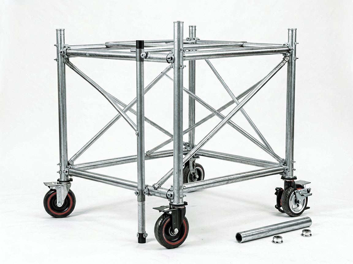
Metal frame mobile scaffolding parts form the core structural and functional elements of temporary elevated work platforms used in construction, maintenance, and industrial applications. These components include frames, braces, casters, platform brackets, locking pins, and adjustable outriggers—each engineered to work together as an integrated system for safe, rapid deployment and repositioning at height.
Unlike fixed scaffolding, mobile systems require parts that balance structural rigidity with mobility and quick-release functionality. Frames are typically manufactured from cold-formed steel tubing with precise dimensional tolerances to ensure square alignment when stacked. Bracing elements—diagonal and horizontal—provide lateral stability against wind loads and worker-induced sway, while casters incorporate dual-lock mechanisms (swivel and brake) to prevent unintended movement during use.
The performance of a mobile scaffold depends on the compatibility and load-path integrity of its individual parts. Frames serve as vertical load carriers, transferring worker and equipment loads down to the casters. Cross braces create triangular rigidity within each bay, preventing racking under lateral forces. Adjustable screw jacks at the base compensate for uneven surfaces, maintaining platform levelness within ±2° as required by OSHA 1926.451(f)(16).
Platform brackets—often U-shaped or hook-style—securely attach work planks to the frame without penetrating the decking material, preserving integrity and allowing rapid replacement. Locking pins, typically made from hardened steel with spring-loaded detents, prevent accidental disengagement of frames and braces under vibration or impact. Outriggers, when deployed, increase the base footprint to reduce overturning moment, particularly important for scaffolds exceeding 4x their minimum base width in height.
Structural components are predominantly made from Q235 or equivalent structural carbon steel, selected for its yield strength (approximately 235 MPa) and ductility under dynamic loading. Tubing diameters range from 38mm to 50mm outer diameter with wall thicknesses between 1.2mm and 2.0mm, chosen based on rated load class (light, medium, or heavy duty per EN 1004:2020). Surfaces are typically hot-dip galvanized (minimum 55µm zinc coating) or powder-coated to resist corrosion in outdoor and humid environments.
Casters combine forged steel frames with polyurethane or rubber treads (shore hardness 90A–95A) to support loads up to 1,000 kg per caster while minimizing floor damage. Braking mechanisms use cam-style or pedal-activated systems that lock both swivel and rotation simultaneously. All load-bearing pins and couplings undergo tensile testing to verify shear strength exceeding 25 kN, with fatigue resistance validated through cyclic load testing (10,000+ cycles at 75% working load).
Interchangeability between manufacturers is limited due to variations in tube spacing, coupling geometry, and locking mechanisms. Most systems follow either a 38mm or 50mm module standard, but even within these, pin diameter, hole spacing, and brace connection angles differ. Buyers must verify that replacement parts match the original equipment manufacturer’s (OEM) frame spacing (commonly 1.5m or 1.8m bay length) and coupling type (e.g., pin-and-claw, wedge-lock, or spring-lock).
Mixing parts from different systems risks misalignment, reduced load capacity, and potential disengagement under load. For this reason, reputable suppliers provide detailed compatibility charts specifying tube dimensions, coupling specifications, and maximum allowable load per configuration. Custom fabrication is available for non-standard bay sizes or specialized applications (e.g., confined spaces, stair towers), but requires engineering review to ensure compliance with local safety regulations.
Load capacity depends on frame height, base dimensions, bracing pattern, and caster rating. A standard single-width scaffold (0.75m wide) with 2m bay length, four levels high, and proper outrigger deployment typically supports a uniformly distributed load of 2 kN/m² (light duty) or 3 kN/m² (medium duty) per EN 1004 Class 3. Maximum platform height is generally limited to 4x the minimum base width when outriggers are not used, increasing to 6x with approved stabilizers.
Exceeding these limits increases deflection beyond allowable (L/200) and raises the risk of instability. Diagonal bracing must be installed in every other bay for scaffolds over 4m tall, and horizontal bracing at every level to prevent torsional twist. Casters must be rated for the total scaffold weight plus live load, with a minimum 3:1 safety factor applied to dynamic loads. Regular inspection of welds, pins, and caster housings is required to detect cracks, deformation, or wear.
| Component | Typical Material | Key Specification | Functional Role |
|---|---|---|---|
| Vertical Frame | Q235 Steel, Ø48.3x2.0mm | Yield Strength ≥235 MPa | Vertical Load Transfer |
| Diagonal Brace | Q235 Steel, Ø38x1.5mm | Length: 2.0m–2.5m | Lateral Stability |
| Caster with Brake | Forged Steel, PU Tread | Load: 1,000 kg, Dual Lock | Mobility & Position Lock |
| Platform Bracket | Stamped Steel, Galvanized | Hook Depth: 40mm | Plank Retention |
| Adjustable Screw Jack | Steel, Acme Thread | Adjustment: 0–300mm | Leveling on Uneven Surfaces |
Proper selection of metal frame mobile scaffolding parts requires understanding not only individual component ratings but also how they interact within the assembled system. Engineers and procurement teams should evaluate compatibility, environmental exposure, load patterns, and frequency of reassembly when specifying parts. Documentation such as test reports, material certificates, and assembly manuals should be requested to verify compliance with regional standards (OSHA, EN 1004, CSA S269.2, or AS/NZS 1576).
For technical inquiries, custom configurations, or compatibility verification with existing systems, contact our engineering team to discuss your project requirements. We provide detailed dimensional drawings, load tables, and material specifications to support informed procurement decisions.





