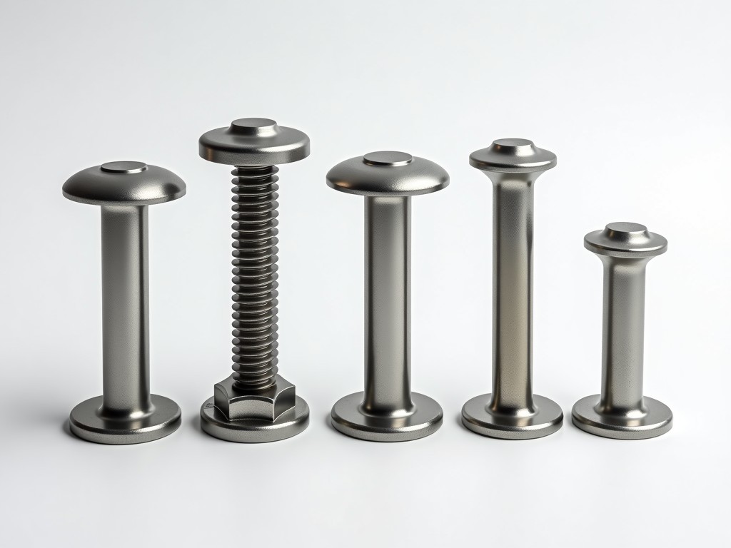
Locking pins are critical safety components in modular scaffolding systems, designed to secure tube and coupler joints under dynamic loads. Their primary function is to prevent accidental disconnection caused by vibration, wind, or worker movement, which could lead to structural failure. Unlike standard pins, locking pins incorporate a mechanical retention feature—such as a spring-loaded ball, detent, or cotter mechanism—that maintains engagement even when subjected to lateral or axial forces. This design reduces reliance on friction alone, which can degrade due to corrosion, paint buildup, or wear over time. For procurement engineers, selecting the correct locking pin involves evaluating load capacity, compatibility with scaffold tube diameters, and environmental exposure.
The load path in a locking pin assembly transfers force from the scaffold tube through the pin’s shank into the retaining mechanism, which then reacts against the coupler body. Most locking pins are engineered to resist shear forces exceeding 15 kN in standard 48.3 mm OD scaffold tubes, with ultimate tensile strength often surpassing 25 kN depending on material and heat treatment. The pin’s diameter—typically 12 mm or 16 mm—is matched to the coupler’s hole tolerance to minimize play while allowing for thermal expansion and ease of insertion. A chamfered or rounded leading edge facilitates alignment during assembly, reducing installation time and the risk of cross-threading or galling in threaded coupler variants.
Retention mechanisms vary by design: spring-loaded balls sit in detents milled into the pin shaft, requiring axial compression to retract; cotter pins rely on physical obstruction after insertion; and twist-lock designs use a cam action to engage a recessed notch. Each method offers trade-offs in installation speed, resistance to vibration loosening, and ease of inspection. Spring-ball systems are common in high-cycle applications due to rapid engagement, while cotter pins are preferred in environments where foreign object debris (FOD) must be minimized, as they have no protruding parts that could snag.
Locking pins are predominantly manufactured from carbon steel (e.g., C45 or 1045) due to its balance of strength, machinability, and cost-effectiveness. For enhanced hardness and wear resistance, pins are often quenched and tempered to achieve a surface hardness of 45–55 HRC. In corrosive environments—such as coastal construction, chemical plants, or marine scaffolds—stainless steel grades like AISI 304 or 316 are specified. Grade 316 offers superior resistance to chlorides and sulfur compounds, making it suitable for offshore or industrial processing facilities where pitting corrosion could compromise retention function over time.
Surface treatments further extend service life. Zinc plating (typically 8–12 µm thickness) provides sacrificial protection in mild atmospheres, while hot-dip galvanizing (55–85 µm) is used for prolonged outdoor exposure. Some manufacturers apply a duplex system: hot-dip galvanizing followed by a powder topcoat for added UV and abrasion resistance. It is important to note that coatings must not interfere with the retention mechanism’s movement; excessive buildup in detent holes or spring cavities can impede function, so tolerances are tightly controlled during plating.
Locking pins are designed to interface with specific coupler types, most commonly those conforming to EN 74, BS 1139, or ANSI/SSFI SC-100 standards. The pin length must accommodate the coupler’s flange thickness plus sufficient engagement depth—usually 20–25 mm beyond the tube wall—to ensure full shear area utilization. Standard lengths range from 60 mm to 100 mm, with variations tied to coupler design (e.g., swivel vs. fixed angle). The pin diameter is critical: undersized pins allow excessive movement, increasing wear and risk of disengagement; oversized pins may not insert or could deform the coupler hole under load.
To ensure compatibility, manufacturers provide detailed dimensional drawings specifying pin diameter, length, head style (e.g., T-handle, L-handle, or flush), and retention feature geometry. Buyers should verify that the pin’s retracted profile (for spring-ball types) does not protrude beyond the coupler face, which could create a snag hazard. In systems where pins are frequently removed and reinserted—such as in facade scaffolding—wear on the detent holes becomes a maintenance consideration, necessitating periodic inspection for elongation or cracking.
Reliability of locking pins is validated through functional and destructive testing. Each batch undergoes dimensional inspection to confirm pin diameter, length, and retention feature depth within ±0.1 mm tolerances. Mechanical testing includes static shear tests applied at a controlled rate (typically 5 mm/min) until failure, with results compared against minimum required loads specified in regional safety standards. For spring-ball pins, retention force is measured—the axial force required to retract the ball against spring pressure—typically ranging from 50 N to 150 N depending on design. This ensures the pin remains engaged under vibration but can still be installed/removed with standard tools.
Fatigue testing simulates cyclic loading conditions experienced in real-world use, often at 70% of ultimate load for 10,000+ cycles to detect early signs of cracking or permanent deformation. Surface hardness is verified via Rockwell testing on cross-sections, and plating thickness is confirmed using magnetic or X-ray fluorescence methods. Visual inspection checks for burrs, sharp edges, or incomplete coating—defects that could compromise safety or usability. Traceability is maintained via batch markings laser-etched on the pin head, enabling recall or investigation if field issues arise.
Locking pins are indispensable in tube-and-coupler scaffolding, where modularity demands frequent assembly and disassembly. In facade scaffolding systems, where workers adjust platforms daily to follow building contours, rapid pin insertion and secure retention improve efficiency without sacrificing safety. In shoring and formwork applications—where vertical loads dominate but lateral forces from concrete pouring or wind still exist—locking pins prevent coupler slip that could lead to uneven settlement or collapse. Their use is especially critical in suspended scaffolding, where failure of a single connection point has catastrophic consequences.
Beyond construction, locking pins are used in temporary staging for events, aircraft maintenance stands, and industrial access platforms. In these settings, load cycles may be lower, but environmental exposure (e.g., UV, moisture, chemicals) or cleanliness requirements (e.g., in food processing or semiconductor facilities) may dictate material choice. For example, stainless steel pins with electropolished finishes are selected in cleanrooms to minimize particulate shedding, while zinc-plated pins suffice for indoor warehouse scaffolding with limited humidity exposure.
| Mechanism | Engagement Force | Vibration Resistance | Inspection Ease | FOD Risk |
|---|---|---|---|---|
| Spring-loaded ball | 50–150 N (retraction) | High | Visual: ball visible when engaged | Low (no protruding parts) |
| Cotter pin | Mechanical stop | Very high | Visual: cotter leg visible | Very low |
| Twist-lock cam | Torque-dependent | Medium | Rotational alignment check | Medium (cam may protrude) |
The table above compares common retention mechanisms across key operational factors. Spring-loaded balls offer a balance of speed and reliability, making them suitable for high-frequency use. Cotter pins provide the highest resistance to vibrational loosening and are favored in safety-critical or long-term installations where minimal maintenance is desired. Twist-lock designs allow tool-free operation but require correct rotational alignment to ensure engagement, introducing a potential for human error if not properly verified. Selection should align with the project’s inspection protocols, maintenance schedule, and environmental conditions.
While standard locking pins cover the majority of scaffolding configurations, customization is available for non-standard tube diameters, specialized coupler geometries, or extended length requirements. For instance, pins with extended shanks are used in couplers with thick gussets or reinforcement plates. Head styles can be modified—such as adding a T-handle for gloved operation or a recessed socket for tamper resistance—based on site-specific needs. Material certification (e.g., EN 10204 3.1) is available upon request for projects requiring traceability to mill source.
When requesting a quotation, buyers should provide: scaffold tube OD, coupler type (fixed, swivel, sleeve), anticipated load conditions (static/dynamic), environmental exposure (indoor/outdoor, chemical, marine), and required quantity. Lead times typically range from 2–4 weeks for stock materials and 6–8 weeks for specialized grades or coatings. Samples are available for validation testing, particularly when substituting materials or modifying dimensions. Packaging options include bulk packs in corrugated cartons (250–500 pcs) or sealed plastic bags for corrosion-sensitive grades, with desiccant included for export shipments to humid climates.
To discuss your specific locking pin requirements for scaffolding systems, including material selection, dimensional compatibility, or testing documentation, please contact our technical team. We can provide detailed drawings, load test reports, and sample units to support your evaluation process.





