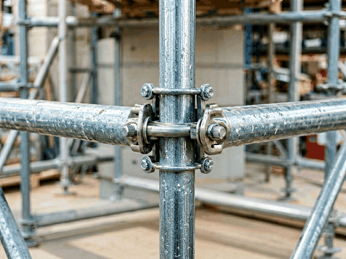
A joint clamp scaffolding coupler is a mechanical connector used to join two scaffold tubes at variable angles, most commonly at 90 degrees, to form rigid lattice structures in temporary access and support systems. Unlike fixed couplers, joint clamps allow adjustment along the tube axis and rotational positioning, enabling adaptation to irregular building facades, complex geometries, or non-standard spacing requirements encountered in renovation, maintenance, and industrial construction.
The coupler consists of two semi-circular jaws, each lined with a replaceable nylon or rubber liner to prevent tube damage, bolted together via high-tensile steel bolts and nuts. Tightening the bolts applies radial pressure to grip the scaffold tubes securely without welding or threading. The design relies on friction and mechanical interlock rather than chemical bonding, allowing disassembly and reuse across multiple projects.
Load capacity is determined by bolt grade, tube material, interface pressure, and friction coefficient between liner and tube. Typical safe working loads for a 48.3mm OD steel tube joint clamp range from 2.2 kN to 3.5 kN in shear, depending on bolt tightening torque (usually 50–70 Nm for M12 grade 8.8 bolts). Tensile resistance is lower, typically 1.0–1.5 kN, as the coupler primarily resists lateral and rotational forces.
Tube compatibility is critical. Joint clamps are designed for specific outer diameters: 48.3mm (standard steel scaffold tube), 42.4mm (lightweight aluminum), or 60.3mm (heavy-duty applications). Using mismatched tubes reduces gripping efficiency and risks slippage. Liners compensate for minor tolerances but cannot overcome significant diameter mismatches.
Adjustment range defines usability. Most joint clamps allow axial slide of up to 50mm along each tube and rotational adjustment of 360 degrees, enabling connections at any angle. Some models feature serrated jaws or offset bolt patterns to prevent rotational creep under sustained load. The adjustment mechanism must maintain clamping force throughout the range without bolt binding or liner extrusion.
The coupler body is typically forged or cast from SG iron (ductile iron) grade GGG40 or higher, offering tensile strength of 400 MPa and elongation of 15% for impact resistance. Alternative materials include cold-rolled steel for higher strength (up to 550 MPa) or aluminum alloys (e.g., A380) for weight-sensitive applications, though aluminum reduces load capacity by approximately 30% due to lower hardness and bearing strength.
Bolts and nuts are usually grade 8.8 steel with zinc electroplating (8–12 µm thickness) for corrosion resistance in moderate environments. For coastal, industrial, or offshore use, hot-dip galvanizing (55–85 µm) or stainless steel (A2-70 or A4-70) is specified. Liners are made from virgin nylon 6 (PA6) or neoprene rubber, selected for abrasion resistance, UV stability, and compression set under cyclic loading.
Service life depends on environmental exposure and usage frequency. In dry, indoor conditions, a well-maintained joint clamp can exceed 10 years or 50+ reuse cycles. In corrosive environments, annual inspection of bolt threads, liner integrity, and body cracking is recommended. Replacement intervals for liners typically range from 6 to 24 months based on visual wear, hardness loss (shore A), or embedded debris.
Joint clamp couplers are essential in facade renovation where building contours deviate from vertical planes. They allow scaffold tubes to follow curved surfaces, such as on silos, tanks, or architectural arches, by enabling incremental angle changes at each joint. This avoids the need for custom-bent tubes or complex node fabrication.
In industrial maintenance, they connect scaffold tubes to irregular equipment geometries—such as heat exchanger bundles, pipe racks, or turbine housings—where fixed-angle couplers would leave gaps or require shimming. The ability to slide tubes axially accommodates thermal expansion or contraction of the supported structure without inducing stress in the scaffold.
They are also used in temporary roofing, grandstands, and event structures where load paths are non-uniform and adjustability during erection is critical. Unlike welded or pinned joints, joint clamps allow real-time correction of misalignment during assembly, reducing rework and improving safety margins.
| Feature | Joint Clamp Coupler | Fixed Swivel Coupler | Putlog Coupler |
|---|---|---|---|
| Adjustability | Axial slide + 360° rotation | 360° rotation only | Fixed 90° only |
| Typical Load Capacity (Shear) | 2.2–3.5 kN | 2.5–4.0 kN | 3.0–4.5 kN |
| Tube Compatibility | Specific OD (e.g., 48.3mm) | Specific OD | Specific OD |
| Setup Time | Moderate (bolt tightening) | Low (bolt tightening) | Low (bolt tightening) |
| Reusability | High (with liner replacement) | High | High |
| Best For | Irregular angles, axial adjustment | Variable angles, fixed radius | Standard right-angle joints |
Note: Values are typical ranges; actual performance depends on tube material, bolt torque, liner condition, and environmental factors.
Each joint clamp undergoes dimensional verification of jaw contours, bolt hole alignment, and liner groove depth using calibrated gauges. Material traceability is maintained from raw ingot to final product, with mill certificates available for ductile iron bodies and bolt batches. Surface coating thickness is measured via magnetic induction or eddy current methods to ensure compliance with corrosion protection standards.
Functional testing includes torque-to-clamp-force correlation on representative tubes, slip resistance under incremental shear load, and cyclic loading to simulate erection and dismantling cycles. Liners are tested for compression set after 24 hours at 70°C and abrasion resistance via Taber testing. Products are not released until all samples in a batch pass visual inspection for cracks, porosity, or flash exceeding 0.5mm.
While third-party certifications like EN 74 or ANSI/SSFI SC100-5/20 are common for scaffold couplers, compliance claims are based on design to those standards. Buyers should request test reports or conformity documentation specific to the intended application and jurisdiction, as local regulations may impose additional requirements on temporary works equipment.
Standard joint clamps are available for 48.3mm, 42.4mm, and 60.3mm tube outer diameters. Non-standard sizes (e.g., 50mm, 76.1mm) can be produced upon request, requiring new tooling for jaw forging and liner extrusion. Minimum order quantities typically apply for custom diameters due to setup costs.
Bolt specifications can be customized: length adjusted for accessibility in tight spaces, grade upgraded to 10.9 or stainless steel for corrosive environments, or replaced with socket head cap screws for low-profile installations. Nut types include standard hex, nylon-lock, or prevailing torque designs to resist vibration loosening.
Liner materials can be specified for extreme conditions: high-temperature nylon (up to 120°C), oil-resistant nitrile rubber, or non-marking silicone for sensitive surfaces. Color coding of liners or bodies is available for site identification or inventory management. Surface treatments such as powder coating (in safety yellow or black) or PTFE coating for reduced friction are offered for specialized applications.
Joint clamps are packed in corrugated cardboard boxes with internal dividers or plastic trays to prevent bolt damage and liner deformation during transit. Standard packaging is 20 or 25 units per box, weighing approximately 8–12 kg depending on size and material. Each box includes a packing list with part number, material specification, and batch traceability code.
For bulk orders, palletization is standard: 40 boxes per pallet (800–1000 units), secured with stretch wrap and corner boards. Export shipments include moisture-barrier lining and desiccant packs to prevent corrosion during sea freight. Marking on external packaging follows ISO 780 standards for handling symbols and includes country of origin, gross/net weight, and safety warnings.
Handling instructions advise against dropping or impacting the coupler body, as this can cause micro-cracks in ductile iron. Bolts and nuts should be kept coated and stored separately if long-term storage is anticipated to prevent galling. Liners are UV-sensitive and should be stored in opaque containers away from direct sunlight.





