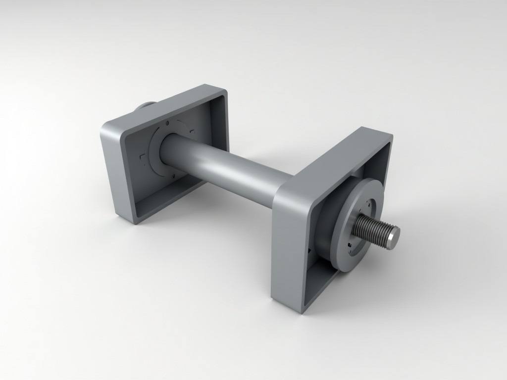
Insulated panel lifting clamps are specialized mechanical handling devices designed to securely grip and transport prefabricated sandwich panels used in building envelopes, cold storage facilities, and industrial enclosures. These clamps address the unique challenges posed by panels with low surface friction, varying thicknesses, and the need to avoid damaging the outer facings or core insulation during lifting operations.
Constructed from high-strength alloy steel with precision-machined contact surfaces, these clamps distribute lifting forces across a broad contact area to prevent localized pressure that could dent metal facings or compress insulation cores. The gripping mechanism typically incorporates non-marring polymer or rubber inserts engineered to maintain friction without leaving residues or marks on coated with low-friction polymers to reduce surface wear on the panel.
Each clamp is rated for a specific working load limit (WLL) based on panel weight, center of gravity, and dynamic loading conditions during transit. Engineers select clamps by calculating the maximum expected load, including safety factors for wind, acceleration, and abrupt stops, ensuring the WLL exceeds the anticipated load by a minimum margin of 5:1 for static loads and 4:1 for dynamic scenarios as per EN 13155 and ASME B30.20 standards.
The clamp body features a forged or machined C-hook or scissor-type geometry that self-adjusts to panel thickness within a defined range, typically 50–200 mm, eliminating the need for manual reconfiguration between panel sizes. This self-adjusting action is achieved through pivoting arms linked by a central load pin, which equalizes force distribution across both gripping jaws when load is applied.
Contact surfaces are lined with virgin nitrile rubber or polyurethane pads, selected for their resistance to UV degradation, oil, and temperature extremes ranging from -40°C to +80°C, ensuring consistent grip performance in both interior and exterior environments. Pad hardness is specified between 60–70 Shore A to balance friction coefficient with surface protection, validated through ASTM D412 tensile testing.
A spring-loaded or cam-actuated locking mechanism maintains clamp engagement even if lifting cable tension fluctuates, preventing accidental release during horizontal movement or when navigating uneven terrain. Release is intentionally designed to require two distinct actions—depressing a safety lever while actuating the release handle—to minimize the risk of inadvertent disengagement.
| Parameter | Typical Value | Notes |
|---|---|---|
| Working Load Limit (WLL) | 500–2000 kg | Per clamp; varies by model and panel thickness range |
| Panel Thickness Range | 50–200 mm | Self-adjusting; custom ranges available |
| Clamp Weight | 8–18 kg | Dependent on WLL and material thickness |
| Body Material | Quenched and tempered alloy steel (e.g., 4140) | Minimum tensile strength: 1000 MPa |
| Pad Material | Nitrile rubber or polyurethane | 60–70 Shore A; non-marking |
| Operating Temperature | -40°C to +80°C | Continuous; intermittent up to +100°C |
| Safety Factor | 5:1 (static), 4:1 (dynamic) | Complies with EN 13155 and ASME B30.20 |
In cold storage construction, insulated panel lifting clamps enable the safe and efficient installation of PIR or PUR core panels used for walls, ceilings, and flooring systems. The clamps’ ability to grip without penetrating the vapor barrier or damaging the facings ensures thermal integrity is maintained, preventing moisture ingress that could compromise insulation performance over time.
For cleanroom and pharmaceutical facilities, where panel surfaces must remain uncontaminated, the non-marking pads prevent particulate shedding or chemical transfer from the clamp to the panel. This is critical in ISO Class 5–8 environments where even minimal surface contamination can lead to product rejection or regulatory non-compliance.
In modular building and prefabrication yards, these clamps support high-cycle handling of panels during stacking, loading, and unloading operations. Their rapid engagement and release mechanism reduces cycle time compared to vacuum lifters or strap-based systems, particularly in high-volume production lines where hundreds of panels are moved daily.
Clamp selection begins with identifying the panel’s core material (e.g., EPS, XPS, PIR, PUR, mineral wool) and facing type (e.g., pre-painted steel, aluminum, fiberglass-reinforced polymer), as these influence surface friction and susceptibility to damage. The required WLL is calculated by multiplying the panel’s area by its unit weight, then applying dynamic load factors based on handling method (e.g., forklift vs. crane) and site conditions.
Customization options include adjusted jaw profiles for non-standard panel geometries, extended throat depth for deep-reach applications, and alternative pad materials such as silicone for high-temperature environments or anti-static compounds for electronics manufacturing zones. Load indicators or RFID tags can be integrated for traceability in automated logistics systems.
Surface treatments such as hot-dip galvanizing or zinc-nickel plating are available for corrosive environments like coastal installations or chemical processing plants, extending service life by reducing oxidation of the load-bearing components. All custom variants undergo finite element analysis (FEA) to validate stress distribution under rated load before prototype fabrication.
Each lifting clamp undergoes proof load testing at 2× the rated WLL for a minimum duration of 30 seconds, with no permanent deformation or crack initiation permitted. This test is conducted on a calibrated hydraulic system with load cell verification traceable to national standards, and results are documented in a test certificate accompanying each unit.
Non-destructive evaluation (NDE) includes magnetic particle inspection (MPI) for surface and near-surface flaws in critical load paths, particularly at welds, pin holes, and stress concentration areas. Ultrasonic testing (UT) is applied to forged components to detect internal inclusions or laminations that could compromise tensile strength.
Functional verification involves cycling the clamp through 100 full load/unload sequences under rated conditions to assess wear on pivot points, pad retention, and locking mechanism reliability. Pad adhesion is tested per ASTM D429 to ensure bonding strength exceeds 1.5 MPa, preventing delamination during repeated use in outdoor environments.
Before each use, inspect the clamp for signs of wear, corrosion, or damage to the gripping pads, load pins, and locking mechanisms. Pads showing cracking, hardening, or loss of elasticity must be replaced immediately, as degraded friction properties can lead to slippage under load. Never use a clamp with missing or improperly installed safety components.
Ensure the panel is positioned so that the load acts vertically through the clamp’s centerline to avoid inducing bending moments on the jaw arms. Off-center loading reduces effective capacity and increases stress on one side of the clamp, potentially leading to premature failure. Use a spreader bar or lifting beam when handling long or flexible panels to maintain load distribution.
Store clamps in a dry, protected environment when not in use to prevent corrosion of uncoated surfaces. Avoid exposure to solvents, acids, or prolonged UV radiation, which can degrade polymer pads. Lubricate pivot points periodically with a high-pressure, molybdenum-disulfide-based grease to maintain smooth operation and prevent galling.
For technical specifications, customization requests, or quotation assistance, contact our engineering team to discuss your specific panel handling requirements.
Request Technical Consultation




