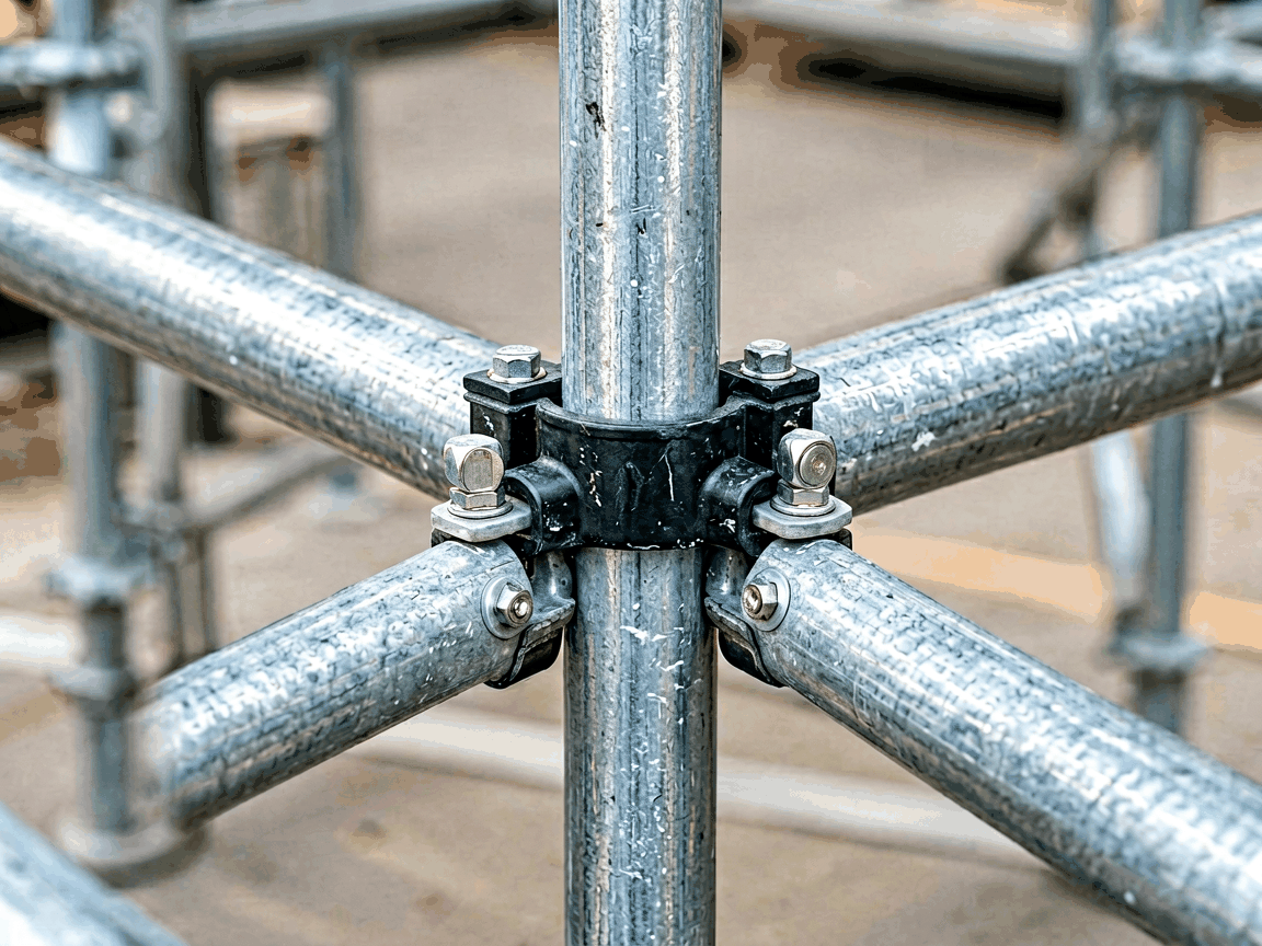
A half coupler scaffolding clamp is a fixed-type connection component designed to join two scaffolding tubes at a 90-degree angle, where one tube acts as the ledger or transom and the other as the standard or vertical upright. Unlike swivel couplers, half couplers provide a rigid, non-rotating joint that resists lateral and torsional loads, making them essential for creating stable, load-bearing frameworks in temporary support structures. These clamps are engineered to grip the scaffolding tube through a forged or pressed steel body that deforms slightly under bolt tension to create a frictional lock, preventing slip under dynamic site conditions. The design adheres to international standards such as EN 74 and BS 1139, ensuring dimensional compatibility with standard 48.3mm outer diameter scaffolding tubes. Half couplers are typically used in conjunction with ledgers, braces, and transoms to form the primary grid of a scaffolding system, where their fixed angle maintains structural orthogonality critical for platform alignment and load distribution. Their simplicity and reliability make them a foundational element in both tube-and-coupler and system scaffolding applications across construction, maintenance, and industrial access projects.
Half coupler bodies are manufactured from hot-rolled structural steel grades such as S275JR or S355JR, selected for their yield strength (minimum 275 MPa or 355 MPa) and ductility, which allows controlled deformation during installation without cracking. The steel is formed via drop forging or precision pressing to achieve the clamp’s jaw geometry, followed by heat treatment to homogenize grain structure and enhance fatigue resistance under cyclic loading. Bolts and nuts are typically made from property class 8.8 carbon steel, featuring a minimum tensile strength of 800 MPa and yield strength of 640 MPa, ensuring the fastener can develop sufficient clamping force before yielding. Surface treatment involves hot-dip galvanization per EN ISO 1461, applying a zinc coating of at least 55 μm thickness to provide sacrificial corrosion protection in humid, alkaline, or chemically exposed environments. This combination of base material, fastener grade, and coating delivers a connection capable of sustaining safe working loads of up to 6.2 kN per coupler in shear and 3.6 kN in tension, as validated through standard tensile and slip tests.
The half coupler is designed to fit scaffolding tubes with a nominal outer diameter of 48.3mm, accommodating tolerances defined in EN 10219-2 (hot-finished) or EN 10210-1 (cold-formed) for seamless and welded structural hollow sections. The internal jaw opening measures approximately 51mm to allow insertion of the tube, while the bolt centerline is positioned 22mm from the tube’s outer surface to optimize leverage and minimize eccentric loading on the fastener. Overall dimensions typically range from 75mm in width (perpendicular to the tube axis) to 95mm in height (parallel to the tube axis), with a projection of 30mm beyond the tube’s centerline to avoid interference with adjacent components. The bolt used is usually an M16x55mm hex head bolt with a matching nut and washer, selected to provide adequate thread engagement and bearing area under torque. These dimensions ensure compatibility with standard scaffolding tubes from major manufacturers and allow interchangeability within mixed-system applications where tube conformity is maintained.
The safe working load (SWL) of a half coupler is determined through laboratory testing that simulates real-world site conditions, including static and dynamic loads, torsion, and combined shear-tension scenarios. Standard EN 74 testing applies a gradual load until slip or deformation occurs, with the SWL defined as the failure load divided by a safety factor of 1.6 for slip and 2.0 for tensile failure. Typical SWL values are 6.2 kN for lateral shear (ledger to standard), 3.6 kN for axial tension (uplift resistance), and 4.5 kN for compressive loads along the tube axis. These values assume proper installation: the tube must be clean, free of grease or paint, and the bolt torqued to 50–65 Nm using a calibrated wrench. Over-torquing can damage the tube or strip threads, while under-torquing reduces frictional resistance and increases slip risk. Designers must account for load eccentricity, dynamic amplification factors from wind or personnel movement, and the cumulative effect of multiple couplers in a bay when calculating scaffold stability.
Production begins with cutting steel billets to length, followed by heating and forging in dies to form the coupler’s two jaws and bolt hole geometry. Forged parts are then trimmed, punched, and subjected to normalizing or quenching and tempering to achieve uniform mechanical properties. Each coupler undergoes dimensional inspection using gauges to verify jaw opening, bolt hole alignment, and overall proportions before proceeding to threading (if applicable) and assembly with the bolt, nut, and washer. Hot-dip galvanizing is performed after machining to ensure complete coverage, including threads and internal surfaces, with coating thickness verified via magnetic induction probes. Final quality checks include visual inspection for defects, proof load testing on a statistical sample basis (typically 1 per 500 pieces), and torque-slip testing to validate clamping performance. Traceability is maintained through batch marking, allowing identification of raw material source, heat treatment lot, and inspection records for audit purposes.
Half couplers are primarily used to connect horizontal ledgers or transoms to vertical standards at right angles, forming the bays and lifts of a scaffolding structure. In facade scaffolding, they secure ledgers that support working platforms, ensuring the horizontal members remain fixed against lateral push or pull from wind, material storage, or worker movement. In shoring and formwork applications, half couplers attach horizontal beams to vertical posts to support concrete slabs during curing, where rigidity prevents deflection under wet concrete load. They are also used to install diagonal braces by connecting the brace end to a standard via a half coupler, though swivel couplers are often preferred at the brace’s mid-point for angular adjustment. In suspended scaffolding, half couplers may anchor tie-back tubes to building structures or support beams, providing a fixed point for load transfer. Their fixed-angle nature makes them unsuitable for joints requiring variable angles, but ideal for repetitive, orthogonal connections where speed, reliability, and predictability are prioritized on complex job sites.
Half couplers differ from swivel couplers in their fixed 90-degree orientation, which eliminates rotational freedom but increases resistance to twisting moments at the joint. Swivel couplers allow 360-degree adjustment, making them suitable for bracing or irregular geometries, but they exhibit lower slip resistance under torsional load due to the moving joint interface. Sleeve couplers (also called pin or spigot couplers) join two tubes end-to-end axially and are not designed for transverse connections like half couplers. When comparing load capacity, half couplers generally offer higher shear strength than swivel couplers of similar size because the fixed joint distributes load more evenly across the frictional interface, whereas swivel couplers rely on a smaller contact area that can concentrate stress. In terms of installation, half couplers are faster to apply than sleeve couplers, which require precise tube alignment and insertion depth, but slower than swivel couplers when angular adjustment is needed. The choice between coupler types depends on the structural geometry, load direction, and adjustability requirements of the specific scaffolding bay.
| Parameter | Typical Value | Notes |
|---|---|---|
| Scaffolding Tube OD | 48.3 mm | Standard size per EN 10219/10210 |
| Half Coupler Width | 75 mm | Perpendicular to tube axis |
| Half Coupler Height | 95 mm | Parallel to tube axis |
| Bolt Size | M16 x 55 mm | Property class 8.8 |
| Recommended Bolt Torque | 50–65 Nm | Ensures adequate clamping force |
| SWL – Shear (Ledger to Standard) | 6.2 kN | EN 74 tested, safety factor 1.6 |
| SWL – Tension (Uplift) | 3.6 kN | Safety factor 2.0 |
| Zinc Coating Thickness | ≥55 μm | Hot-dip galvanized per EN ISO 1461 |
| Material – Body | S275JR or S355JR | Hot-rolled structural steel |
| Material – Bolt/Nut | Property class 8.8 | Carbon steel, quenched and tempered |
While standard half couplers conform to EN 74 dimensions for interchangeability, certain project requirements may warrant modifications. Customization options include alternative bolt lengths (e.g., M16x70mm for use with thicker gauge tubes or additional washers), stainless steel fasteners (A2 or A4 grade) for corrosive environments such as chemical plants or marine settings, and specialized coatings like zinc-nickel or epoxy for enhanced resistance to salt spray or industrial pollutants. Some manufacturers offer half couplers with reinforced webs or gussets to increase moment resistance in high-load applications, though such designs may deviate from standard dimensions and require verification for compatibility. Thread protectors or nylon inserts can be added to bolts to prevent loosening under vibration, particularly in long-term installations or areas exposed to machinery resonance. All customizations are subject to minimum order quantities and must be evaluated for impact on load capacity, dimensions, and certification status, with test data available upon request for engineered solutions.
Industrial buyers should verify that half coupler scaffolding clamps are manufactured under a quality management system certified to ISO 9001, ensuring consistent process control from raw material receipt to final shipment. Reputable suppliers provide mill test certificates (MTCs) for the steel used in the coupler body and fastener components, confirming chemical composition and mechanical properties meet the specified grade. Finished couplers are often tested to EN 74 or ANSI/SSFI SC-100-5/05 standards, with test reports available for batch-specific performance in slip, tensile, and ductility assessments. Markings on the coupler typically include the manufacturer’s ID, material grade, standard conformity (e.g., “EN 74”), and a batch or traceability code. Surface finish is inspected for uniform galvanization, absence of runs or bare spots, and proper thread protection. Packaging is designed to prevent damage during transit, with couplers bundled in water-resistant straps or placed in labeled cartons to maintain traceability and ease of handling on-site.
For technical inquiries, customization requests, or quotation details regarding half coupler scaffolding clamps, please contact our engineering team. We provide full documentation, including material certifications, test reports, and dimensional drawings, to support your procurement and safety compliance requirements.
Contact Us for Technical Support




