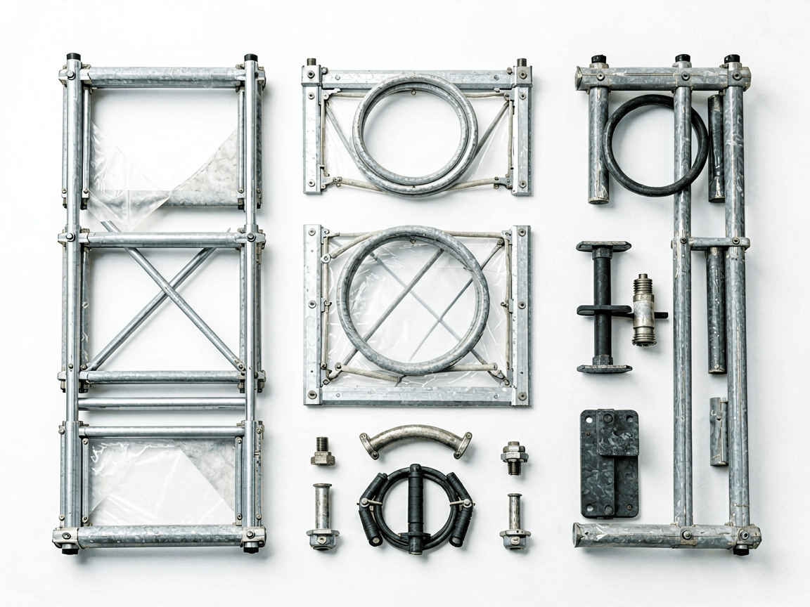
H frame scaffold systems consist of standardized interlocking components designed for rapid assembly, structural stability, and adaptability across construction, maintenance, and industrial access applications. The modular nature allows engineers to configure working platforms at various heights while maintaining load-bearing integrity under dynamic and static conditions. Each component is engineered to interface precisely with mating parts, minimizing play and ensuring predictable performance under specified load cases.
The primary structural elements include vertical frames, horizontal braces, diagonal braces, base jacks, and platform brackets. Vertical frames form the load-bearing towers, typically fabricated from cold-formed steel tubing with welded gussets at joint intersections to resist racking forces. Horizontal and diagonal braces create triangulated stability, transferring lateral loads—such as wind or worker-induced sway—into the vertical members through pinned or bolted connections. Base jacks provide adjustable height compensation for uneven substrates, while platform brackets support working decks at designated lift points.
Material selection directly influences service life, weight, and corrosion resistance. Structural tubing commonly uses ASTM A500 Grade B or equivalent steel with a minimum yield strength of 350 MPa, balancing ductility and stiffness. Surface treatments include hot-dip galvanization per ISO 1461 for outdoor exposure or powder coating for controlled environments. Connection hardware—pins, clips, and bolts—typically employs grade 8.8 steel with zinc plating to prevent galling during repeated assembly cycles.
Understanding the role of each part enables correct specification and reduces risks of misassembly or overloading. The vertical frame is the primary load path, transferring platform and worker loads to the foundation via base jacks. Its vertical legs are spaced to accommodate standard platform widths, with integrated lugs or sockets for brace attachment at 500 mm vertical intervals. Diagonal braces, usually installed in opposing pairs, prevent racking by converting lateral forces into axial tension and compression within the brace members.
Horizontal braces, also known as ledgers, run parallel to the working surface and prevent inward/outward buckling of the vertical frames. They are typically shorter than diagonal braces and connect at the same nodal points, forming a rectangular grid when viewed in elevation. Base jacks consist of a threaded spindle within a steel socket, allowing vertical adjustment of up to 300 mm to accommodate slope or settlement. Swivel base jacks include a pivoting mechanism for non-perpendicular substrates.
Platform brackets, or U-heads, are forged or pressed steel fittings that attach to the vertical frame lugs to support scaffold planks or steel decks. They feature a captive design to prevent accidental disengagement and often include a safety lip to retain decking under uplift forces. Locking pins, spring clips, or wedge bolts secure braces and brackets to the frame, with designs optimized for tool-free installation while maintaining shear and tensile capacity per EN 1004 or OSHA 1926 Subpart L requirements.
Standard H frame scaffold components are manufactured to accommodate common platform heights and bay dimensions, but project-specific constraints often require modifications. Frame height, leg spacing, brace length, and connection type can be adjusted based on access needs, load conditions, or site geometry. Customization does not compromise interchangeability with standard parts when mating interfaces remain unchanged.
| Component | Typical Range | Customizable Parameters |
|---|---|---|
| Vertical Frame | 0.5m to 2.0m height | Leg spacing, tube diameter, wall thickness, lug pattern |
| Diagonal Brace | 1.8m to 3.0m length | Length, end fitting type, tube size |
| Horizontal Brace | 0.6m to 1.5m length | Length, connection style, reinforcement |
| Base Jack | 300mm adjustment | Spindle diameter, thread pitch, base plate size, swivel vs fixed |
| Platform Bracket | Standard duty | Load rating, deck retention mechanism, material finish |
Load capacity depends on frame geometry, brace configuration, and connection integrity. A typical single-bay H frame scaffold with standard 1.9m frames and full bracing can support uniformly distributed loads of up to 2.0 kN/m² on working platforms when erected per manufacturer guidelines. Concentrated loads, such as material stacks or equipment, require additional bracing or reduced bay widths. Engineering review is recommended for configurations exceeding standard height-to-base ratios or supporting dynamic loads from machinery.
H frame scaffold systems are selected not merely for their availability but for their suitability to specific access challenges. In petrochemical plants, they provide safe access to elevated piping and vessel exteriors during turnarounds, where corrosion-resistant finishes and non-sparking components may be specified. In power generation, they support boiler inspection and turbine maintenance, requiring configurations that accommodate uneven foundations and restricted laydown areas. The modular design allows reconfiguration as work progresses, minimizing dismantling and reassembly time.
In bridge construction and repair, H frame scaffolds are used for under-deck access and pier work, where adjustable base jacks compensate for sloping abutments and diagonal bracing resists wind loads from open exposures. Shipyards utilize them for hull fabrication and painting, benefiting from rapid erection and the ability to stack multiple levels for full circumnavigation. The standardized parts inventory simplifies logistics and reduces the need for specialized training across shifts.
Industrial facilities such as refineries, pulp mills, and automotive plants use H frame scaffolding for routine maintenance of overhead conveyors, cranes, and structural steel. The ability to create suspended platforms or cantilevered extensions allows access to areas without ground support. Integration with safety systems—such as toe boards, guardrails, and personal fall arrest anchors—is facilitated by standardized mounting points on the frame and brackets.
Consistent performance begins with raw material traceability and precise fabrication. Tube dimensions are monitored during forming to ensure ovality and wall thickness remain within tolerances that affect buckling resistance. Welded joints undergo visual inspection and, where critical, non-destructive testing to confirm fusion and absence of cracks. Connection lugs are machined or forged to exact dimensions to prevent excessive play or binding during pin insertion.
Surface preparation before galvanizing or coating includes degreasing, pickling, and phosphating to ensure adhesion and uniform coverage. Galvanized coatings are measured for thickness compliance, typically targeting 55–85 μm for long-term outdoor exposure. Final assembly checks include verifying pin fit, brace alignment, and bracket levelness. Packaging methods—such as bundling with steel straps or placing in reusable pallets—protect components during transit and storage.
Documentation accompanying each batch includes material test certificates, coating reports, and inspection records. Traceability tags link individual components to production lots, enabling retrospective analysis if field performance deviates from expectations. Manufacturers may offer third-party certification to EN 1004, ANSI/SSFI SC100.5-04, or local equivalents upon request, providing independent verification of design and manufacturing controls.
For technical specifications, customization requests, or quotation details, contact our engineering team.





