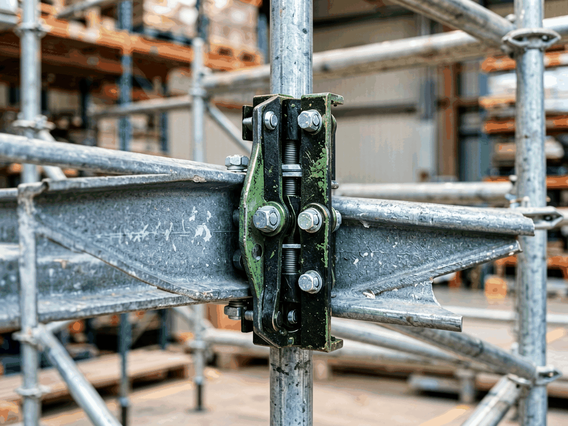
The Gravlock girder coupler scaffold clamp is a specialized connection device engineered to securely attach scaffolding systems to structural steel beams or girders without requiring welding, drilling, or permanent modifications to the host structure. Its primary function is to transfer lateral and vertical loads from the scaffold to the girder through a mechanical locking mechanism that engages the flange of the beam. This enables rapid, reversible installation in environments where structural integrity must be preserved, such as in occupied buildings, historical structures, or temporary industrial facilities.
The clamp operates on a cam-locking principle where a hardened steel jaw pivots to grip the girder flange when actuated by a lever or bolt mechanism. As force is applied to the lever, the jaw rotates into contact with the flange, creating a frictional and mechanical interlock that resists both slip and uplift. The design distributes bearing stress across a hardened contact pad to prevent localized deformation of the girder flange, which is critical when working with thinner or high-strength steel sections commonly found in modern construction.
Unlike bolt-through clamps that require access to both sides of the girder, the Gravlock design is single-sided, allowing installation from one face only—particularly advantageous when the girder is adjacent to a wall, another structural member, or enclosed within a shaft. The self-tightening feature ensures that under increasing load, the clamping force increases proportionally, enhancing stability without requiring re-torquing during use.
The main body is typically manufactured from ductile iron (ASTM A536 Grade 65-45-12) or forged carbon steel (ASTM A36 equivalent), selected for its high tensile strength, impact resistance, and ability to withstand repeated load cycles without fatigue cracking. The locking jaw and pivot pins are made from through-hardened alloy steel (e.g., 4140 or 8620) with surface hardness exceeding HRC 50 to resist wear and galling during cyclic loading. All load-bearing components undergo stress-relief annealing after machining to minimize residual stresses that could lead to distortion over time.
Corrosion protection is achieved through hot-dip galvanizing (per ASTM A153) or a zinc-rich primer with epoxy topcoat, providing a minimum coating thickness of 85 µm for outdoor exposure. In marine or chemical environments, optional stainless steel (316L) versions are available upon request, though these are typically reserved for specialized applications due to cost and weight considerations. The design avoids crevices and traps where moisture or debris could accumulate, reducing the risk of concealed corrosion.
Standard Gravlock couplers are rated for safe working loads (SWL) of up to 25 kN (approximately 5,600 lbs) per clamp when installed on girder flanges ranging from 100 mm to 220 mm in width and up to 25 mm in thickness. These values are derived from static testing per EN 12811-1 and ANSI/ASSE A10.8 standards, with a minimum safety factor of 4:1 against ultimate failure. The clamp is designed to resist both downward loads (from scaffold weight and live loads) and uplift forces (from wind or seismic excitation), making it suitable for use in facade retention, shoring, and temporary roof support systems.
Applications include supporting formwork for concrete pours on steel-framed buildings, providing access platforms for bridge maintenance, erecting suspended scaffolds in atriums or lobbies, and creating temporary walkways over open floor plates during renovation. The clamp is particularly valued in retrofit projects where drilling into structural members is prohibited by code or client specification, and where rapid dismantling is required to minimize disruption to ongoing operations.
Installation requires only a standard wrench or ratchet to actuate the locking lever—no specialized tools are needed. The clamp is placed over the girder flange, and the lever is rotated until the jaw makes firm contact with the flange surface. A visible indicator (often a colored mark or alignment notch) confirms full engagement. Adjustment is achieved through a threaded screw or cam mechanism that accommodates flange thickness variations within the specified range, typically allowing ±3 mm of adjustment without removing the clamp from the girder.
Once installed, the clamp maintains its position under vibration and thermal cycling due to the self-locking geometry of the mechanism. Removal is performed by reversing the lever action, which retracts the jaw and releases the flange. No damage to the girder surface occurs under normal use, as the contact surfaces are designed to distribute pressure and avoid scoring. Reuse is expected for hundreds of cycles, provided the jaw and contact pad show no signs of cracking, excessive wear, or deformation during routine inspection.
Each Gravlock coupler undergoes 100% dimensional inspection of critical interfaces (jaw width, pivot pin diameter, lever throw) using calibrated gauges before leaving the factory. Material certificates are maintained for all heat-treated components, and batch traceability is maintained via laser-etched serial numbers on the main body. Load testing is performed on a statistical sampling basis (typically 1 in 500 units) using hydraulic rams to verify ultimate strength and deformation characteristics.
Visual inspection checks for casting defects, surface cracks, coating uniformity, and correct assembly of springs and pins. Functional testing includes cycling the lever through 50 full open-close operations to ensure smooth operation and consistent locking torque. Units failing any check are segregated and reworked or scrapped. Documentation, including material certifications and test summaries, is available upon request for project audits or third-party inspections.
| Attachment Method | Installation Access | Structural Modification | Reusability | Typical Use Case |
|---|---|---|---|---|
| Gravlock Girder Coupler | Single-sided | None | High (100+ cycles) | Occupied buildings, retrofit, temporary access |
| Bolt-Through Clamp | Double-sided | Requires drilling | Medium (50 cycles) | New construction, exposed steel |
| Welded Bracket | Single-sided | Permanent welding | Low (single use) | Permanent structures, heavy-duty lifts |
| Friction-Based Clamp | Single-sided | None | Medium | Light-duty, indoor only |
Note: Values represent typical performance. Actual capacity depends on girder grade, flange condition, and installation accuracy. Consult engineering datasheets for project-specific derating factors.
While standard models cover the majority of scaffolding-to-girder applications, modifications are available to suit non-standard geometries or extreme environments. Jaw profiles can be adapted for tapered flanges, angled connections, or girder webs where flange access is obstructed. Lever lengths and actuation torque can be adjusted to accommodate confined spaces or gloved-hand operation in cold climates. Surface treatments beyond galvanizing—such as duplex coatings or nitriding—are offered for high-abrasion or corrosive settings.
For projects requiring certified load data, third-party testing reports (e.g., from TÜV, SGS, or local accreditation bodies) can be arranged for specific girder configurations. Custom branding or laser marking for asset tracking is also available. Minimum order quantities for non-standard variants typically start at 50 units, with lead times ranging from 4 to 6 weeks depending on complexity and material availability. All customizations are subject to engineering review to ensure compliance with applicable safety standards.
Routine inspection should focus on three areas: jaw contact surfaces for wear or cracking, pivot pins for looseness or galling, and the lever mechanism for smooth operation and return action. Any deformation exceeding 10% of original dimensions, visible cracks, or loss of locking tension warrants removal from service. Lubrication of pivot points with a dry-film lubricant (e.g., MoS₂-based) is recommended in high-cycle or dusty environments to prevent seizing, though grease should be avoided as it can attract abrasive particulates.
Storage should be in a dry, covered area to prevent coating degradation. When transported, couplers should be stacked flat or in dedicated racks to avoid bending the lever arms. With proper care, a Gravlock coupler can remain serviceable for 5–7 years in moderate conditions, or longer in intermittent-use scenarios. End-of-life recycling is straightforward, as the components are primarily ferrous metals with minimal coatings or contaminants.
The Gravlock girder coupler is designed to comply with the performance requirements of EN 12811-1:2003 (Temporary works equipment – Part 1: Scaffolds – Performance requirements and general design) and ANSI/ASSE A10.8-2019 (Safety requirements for scaffolding). While the product itself is not typically certified as a standalone item, it is intended for use within scaffold systems that are assembled and inspected according to local regulations (e.g., OSHA 1926 Subpart L in the U.S., Work at Height Regulations 2005 in the UK).
Manufacturing follows ISO 9001:2015 quality management principles, with documented procedures for material control, process validation, and final inspection. Test reports, material certificates, and conformity declarations are available upon request. The product does not carry CE marking as a standalone component, as scaff couplers fall under the scope of the Machinery Directive only when sold as part of a complete scaffold system; however, all materials and processes align with applicable EU directives for structural components.
For technical inquiries, load capacity validation for specific girder sections, or to request a quotation for standard or customized Gravlock girder coupler scaffold clamps, please contact our engineering team. Provide details on girder dimensions (flange width and thickness), expected loads (vertical and lateral), environmental conditions, and required quantity to ensure accurate product selection and compliance verification.
Request Technical Consultation




