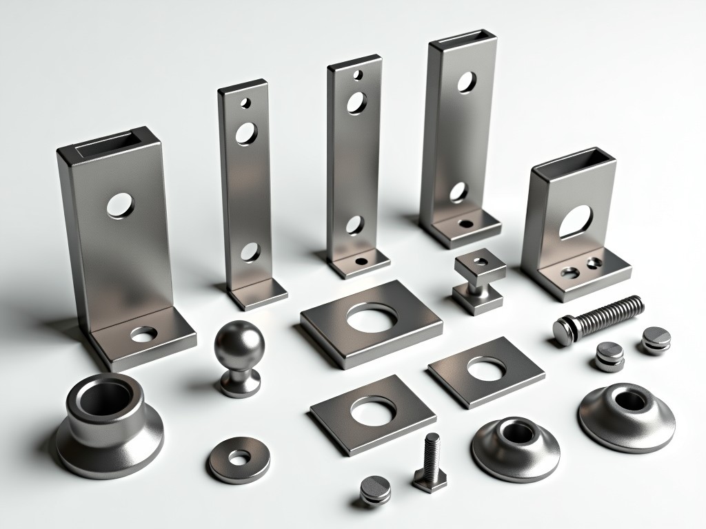
Scaffold brackets are critical load-transfer elements that connect horizontal ledgers or transoms to vertical standards in tubular scaffolding systems. Gates scaffold brackets components refer specifically to the forged or pressed steel fittings designed to interface with Gates-branded scaffolding tube profiles, ensuring dimensional compatibility and structural continuity within the system. These components are not generic fittings; their geometry, hole patterns, and material thickness are engineered to match the specific outer diameter, wall thickness, and longitudinal rib configuration of Gates scaffold tubes, preventing slippage, eccentric loading, or premature fatigue at connection points.
Unlike universal couplers that rely on friction or adjustable jaws, Gates scaffold brackets often employ a positive-locking mechanism—such as a tapered pin, captive wedge, or interleaving lug—to achieve direct metal-to-metal contact. This design minimizes play under cyclic loading and maintains alignment accuracy over repeated assembly and disassembly cycles. The brackets are typically manufactured from hot-rolled structural steel (e.g., S355JR or equivalent) with a minimum yield strength of 355 MPa, selected to withstand the combined tensile, shear, and bending moments imposed during concrete pouring, facade work, or heavy-duty access operations.
Surface treatment is a key differentiator in service life. Standard components undergo hot-dip galvanizing per EN ISO 1461, providing a minimum zinc coating thickness of 55 μm to resist corrosion in outdoor environments. For aggressive conditions—such as coastal exposure, chemical plants, or prolonged wet/dry cycling—alternative finishes like thermal diffusion galvanizing or duplex systems (galvanized + epoxy topcoat) are available upon request, extending maintenance intervals and reducing lifecycle costs.
The structural performance of Gates scaffold brackets is governed by three interdependent factors: connection stiffness, load path efficiency, and stress concentration control. Connection stiffness is achieved through precise mating tolerances—typically ±0.5 mm on tube interface dimensions—ensuring minimal gap when installed. This prevents micro-movement that could lead to fretting fatigue or loosening of locking pins under vibration. Load path efficiency is maximized by aligning the bracket’s centroidal axis with the neutral axis of the scaffold tube, reducing bending moments at the weld or joint interface.
Stress concentrations are mitigated through generous radii (minimum 3 mm) at all internal corners and transitions, avoiding sharp notches where cracks could initiate under cyclic loads. Finite element analysis (FEA) is routinely used in the design phase to validate that peak stresses remain below 60% of the material’s yield strength under the maximum service load defined by EN 12810-1. For example, a standard ledger bracket connecting a 48.3 mm OD tube is designed to safely transfer a 2.2 kN vertical load per connection point with a safety factor exceeding 4:1 against plastic deformation.
Material selection balances strength, ductility, and weldability. The steel used contains controlled levels of carbon (0.14–0.20%) and manganese (0.8–1.4%) to ensure adequate toughness down to -20°C, critical for winter construction scenarios. Phosphorus and sulfur are kept below 0.025% each to minimize brittleness. While some manufacturers use cold-formed steel for cost reasons, Gates scaffold brackets typically employ hot-forged or pressed blanks to refine grain structure and eliminate weak points associated with shear edges or micro-cracks from stamping.
Gates scaffold brackets are not a single part number but a family of components tailored to specific geometric and functional requirements within the scaffold bay. The most common variants include ledger brackets, transom brackets, intermediate brackets, and bracket adapters for specialized applications such as cantilevers, returns, or curved facades. Each variant is defined by its orientation relative to the standard tube, the angle of the connected member, and the presence or absence of auxiliary features like toe-board brackets or ladder tie-offs.
Ledger brackets are designed to connect horizontal ledgers at 90° to the vertical standard, typically featuring a semi-circular cradle that embraces the tube and a vertical web to resist outward push. Transom brackets, while similar in tube interface, often include a horizontal flange to support decking loads and may be asymmetrical to accommodate different board thicknesses. Intermediate brackets—used where a ledger or transom connects mid-span between two standards—must resist torsional twisting and are therefore designed with dual-sided lugs or a central spine to distribute load evenly.
Adapter brackets serve as transitional elements, enabling connection between Gates scaffolding and other systems (e.g., tube-and-coupler or frame scaffolding) or accommodating non-standard angles (e.g., 45° or 60° for stair towers). These components require custom engineering to ensure load compatibility, as they introduce additional moment arms. All variants share the same tube interface specification but differ in geometry, material thickness (ranging from 4 mm to 8 mm depending on load class), and locking mechanism complexity.
| Attribute | Standard Option | Available Alternatives |
|---|---|---|
| Base Material | Hot-rolled S355JR (EN 10025-2) | S355J2 (impact tested), S275JR (lower load), custom alloys upon request |
| Yield Strength (min) | 355 MPa | 275–450 MPa (dependent on grade) |
| Elongation at Break | ≥22% | 18–26% (grade-dependent) |
| Standard Finish | Hot-dip galvanizing (EN ISO 1461) | Thermal diffusion galvanizing, duplex (galvanized + epoxy), powder coating (for indoor) |
| Zinc Coating Thickness | ≥55 μm (average) | 40–120 μm (dependent on process) |
| Temperature Range | -20°C to +40°C (standard) | -40°C to +60°C (with material/finish adjustment) |
The table above summarizes typical material and finish specifications for Gates scaffold brackets components. Exact values are subject to confirmation based on project-specific load classes (per EN 12811-1), environmental exposure categories (per ISO 12944), and required service life. For instance, offshore or petrochemical applications may necessitate S355J2 steel with a duplex coating to meet C5-M corrosion durability requirements, while indoor temporary works might use powder-coated S275JR for cost efficiency where corrosion risk is low.
Manufacturing traceability is maintained through heat batch numbering and optional third-party inspection certificates (e.g., EN 10204 3.1) for material composition and mechanical properties. Galvanizing thickness is verified via magnetic induction probes per EN ISO 1460, with minimum local thickness not falling below 45 μm to ensure compliance. These controls are not optional add-ons but integral to the component’s suitability for safety-critical temporary works.
Gates scaffold brackets components are deployed where precise alignment, repeatable assembly, and predictable load transfer are non-negotiable—such as in high-rise concrete formwork, suspended access platforms, and complex geometric facades. In slip-form construction, for example, the brackets must maintain exact vertical and horizontal tolerances as the formwork is jacked upward; any play or deformation in the connections would accumulate vertically, risking misalignment of walls or cores. The positive-locking interface of Gates brackets minimizes this risk compared to friction-based systems that rely on torque-controlled bolts prone to loosening under vibration.
In facade retention systems during demolition or renovation, brackets are used to tie needleshores or rakers directly to the scaffold standard, transferring lateral loads from unstable walls into the scaffold’s longitudinal bracing. Here, the bracket’s resistance to out-of-plane rotation is critical; a poorly designed connector could allow the tie to pivot under load, reducing its effective lever arm. Gates brackets address this through wide lugs or gussets that increase the moment of inertia about the weak axis, enhancing lateral stability without adding excessive weight.
For curved or radial scaffolds—common in tanks, silos, or architectural arches—special bracket variants are engineered to accommodate varying tube orientations while maintaining a flush interface. These components often feature adjustable lobes or shim-compatible seats to compensate for the changing angle between the standard and the ledger as the scaffold follows a curve. Unlike generic brackets that require tube notching or custom bending, Gates-compatible designs preserve tube integrity, avoiding stress risers from field modifications that could compromise strength.
Quality control begins at raw material receipt, where mill test certificates are verified against the specified steel grade and mechanical properties. Incoming material undergoes spot checks for chemical composition via optical emission spectroscopy (OES) and ultrasonic testing for internal laminations or inclusions—particularly important for forged blanks where internal defects could propagate under stress. Dimensional verification of the blank (e.g., diameter, thickness, flatness) is performed before forging or pressing to ensure the final component will meet interface tolerances.
Post-forming, each bracket undergoes a visual inspection for surface cracks, laps, or incomplete filling—defects that are not always caught by dimensional checks but can drastically reduce fatigue life. Magnetic particle inspection (MPI) is applied to critical weld areas or high-stress zones (e.g., pin holes, lug roots) on a sampling basis, increasing to 100% for components intended for Class 3 or 4 scaffolding (per EN 12811-1) supporting heavy loads like precast concrete or machinery access. Final dimensional inspection focuses on tube interface dimensions, pin hole alignment, and lug flatness using calibrated gauges or coordinate measuring machines (CMM) for complex geometries.
Load testing is not performed on every unit but is conducted on first-article samples and periodically during production to validate design assumptions. Typical proof loads reach 1.5 times the rated service load (e.g., 3.3 kN for a 2.2 kN rated bracket) with no permanent deformation exceeding 0.25 mm. After galvanizing, coating adhesion is tested via knife-edge or pull-off methods (per ISO 2409 or ISO 4624), and zinc thickness is mapped across the component to ensure no thin spots exceed 20% below the mean. All inspection records are retained for traceability and available to customers upon request.
While standard Gates scaffold brackets cover the majority of rectangular and orthogonal scaffold configurations, projects with unique geometric constraints, load profiles, or interface requirements often necessitate adaptation. Customization is not limited to altering dimensions; it involves re-engineering the load path, adjusting stiffness characteristics, or modifying the locking mechanism to suit specific erection sequences or dismantling constraints. For instance, a project requiring frequent reconfiguration of ledger levels might benefit from a quick-release pin system instead of a captive wedge, trading a slight reduction in axial stiffness for significantly faster assembly times.
Common modification requests include changes to lug thickness to accommodate different ledger tube schedules (e.g., 3.2 mm vs. 4.0 mm wall), addition of secondary holes for guardrail or toe-board attachments, or alteration of the bracket’s pitch to match non-standard ledger spacing (e.g., 1.8 m instead of the typical 1.5 m or 2.0 m). In cases where the scaffold interfaces with existing structures—such as anchoring to a concrete column via a bracket—custom flange plates or bolt patterns are integrated into the design, transforming the bracket into a hybrid connection component.
Engineering support for customization includes providing 3D models (STEP or IGES) for interference checks, performing supplemental FEA to validate the modified design under expected loads, and generating fabrication drawings that specify weld symbols, surface preparation requirements, and inspection hold points. Lead times for non-standard components typically range from 3 to 6 weeks, depending on complexity and material availability, and are communicated early in the quotation phase to avoid schedule impacts. All custom components undergo the same quality assurance protocol as standard parts, ensuring no compromise in reliability.
For technical inquiries, customization requests, or detailed specification sheets regarding Gates scaffold brackets components, please contact our engineering team.
Request Technical Consultation




