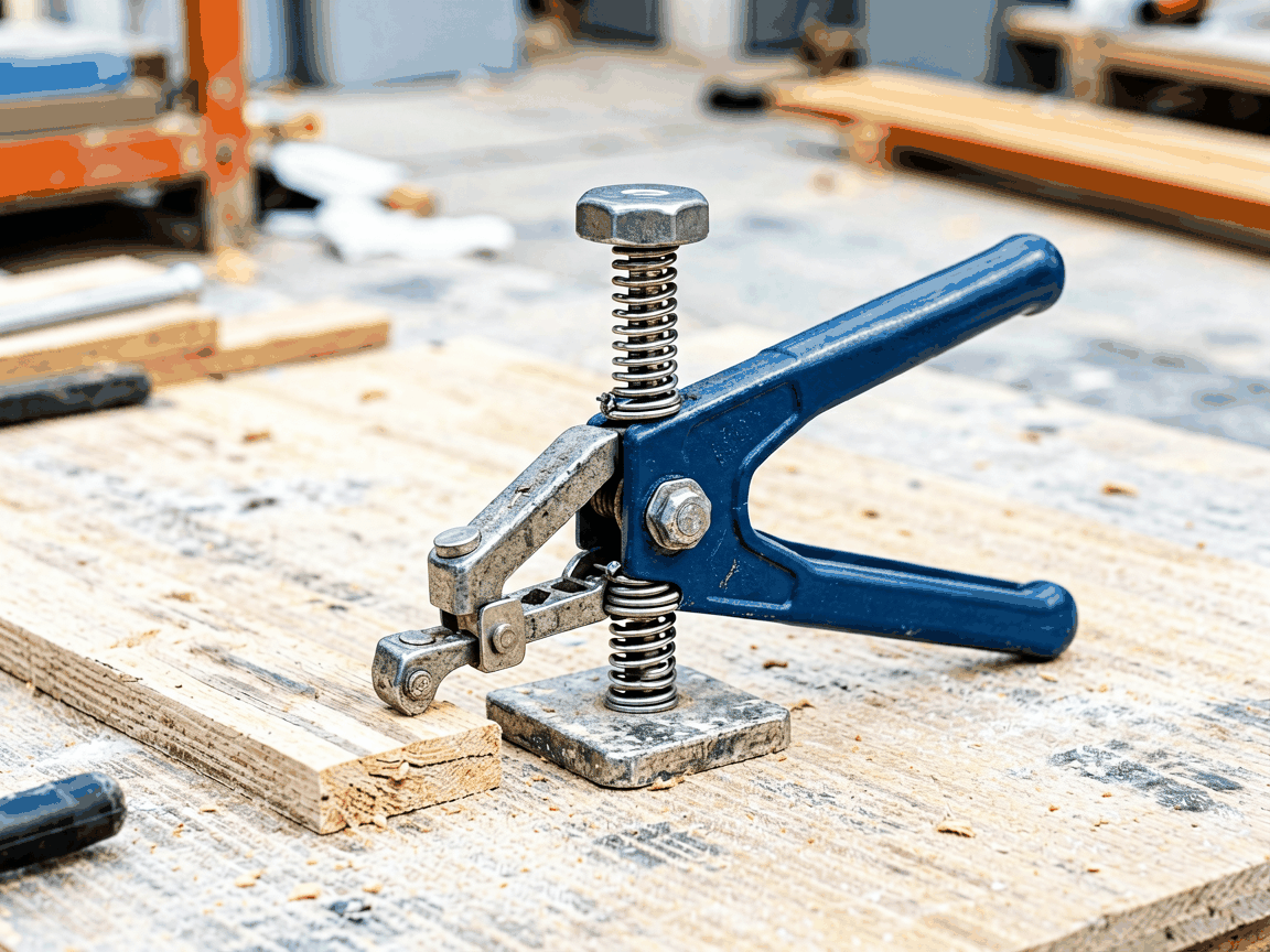
The formwork rapid spring mason clamp is a specialized temporary fastening device used to secure formwork panels to masonry substrates during concrete placement. It combines a spring-loaded jaw mechanism with a threaded adjustment screw to provide quick attachment and release without damaging the substrate or requiring welding or drilling.
The clamp consists of a fixed base plate with a spring-loaded movable jaw that applies clamping force through compression of a helical spring. Rotation of the adjustment screw advances or retracts the jaw, allowing rapid positioning against the formwork panel. The spring maintains constant pressure even if the substrate settles slightly during curing, preventing gap formation that could lead to concrete leakage.
Unlike wedge or screw-only clamps, the spring mechanism compensates for minor variations in panel thickness or substrate irregularity, maintaining consistent clamping force across the contact surface. Release is achieved by reversing the screw rotation, which retracts the jaw against the spring force, allowing the panel to be removed without prying or hammering.
The clamp body is typically manufactured from forged carbon steel (grade C45 or equivalent) to withstand repeated impact and cyclic loading during formwork erection and stripping. The spring component is made from oil-tempered silicon manganese steel (such as 60Si2Mn) to maintain elastic properties over thousands of cycles. All load-bearing surfaces are hardened to HRC 40-45 to resist wear from abrasive concrete particles and formwork edge contact.
Surface treatment includes zinc electroplating (minimum 8μm thickness) or hot-dip galvanizing for corrosion resistance in humid or alkaline environments. For applications involving prolonged exposure to wet concrete or deicing salts, stainless steel variants (AISI 304 or 316) are available upon request, though at higher cost and slightly reduced hardness.
The spring mechanism delivers a consistent clamping force between 1.8 kN and 2.5 kN depending on model and spring preload. This range is sufficient to resist formwork bulging pressures from typical concrete pours (up to 40 kPa) when clamps are spaced at 600 mm intervals along the panel edge. Force output remains stable within ±10% over the adjustment range due to the spring’s near-linear force-deflection characteristic in the working stroke.
The adjustment screw provides 25 mm of linear travel, accommodating formwork panel thicknesses from 15 mm to 40 mm. Thread pitch is typically 3 mm (coarse thread) to allow fast adjustment with minimal rotation—approximately 8 turns for full range—reducing installation time compared to fine-thread alternatives. A captive swivel pad on the jaw tip ensures even pressure distribution and prevents marring of softwood or plywood formwork faces.
Installation begins by positioning the formwork panel against the masonry substrate (concrete, brick, or block). The clamp base is placed on the masonry surface, and the jaw is retracted via the screw to clear the panel edge. The panel is then brought into contact with the jaw, and the screw is rotated clockwise to advance the jaw until firm contact is made. No torque wrench is required; operators rely on tactile feedback and visual alignment.
For optimal load distribution, clamps should be installed at intervals not exceeding 600 mm along vertical formwork edges and at corners where stress concentrations occur. Over-tightening beyond the spring’s designed stroke can cause permanent deformation or reduced elastic recovery; a visual indicator (such as a marked line on the screw) helps prevent over-rotation. Removal follows the reverse sequence: counterclockwise rotation retracts the jaw, allowing the panel to be lifted clear.
This clamp is primarily used in residential and light commercial construction where concrete walls, columns, or beams are formed against existing masonry walls or temporary block backup. It eliminates the need for tie rods through the substrate or drilling anchor holes, preserving the integrity of finished masonry surfaces in renovation or retrofit projects.
Common applications include forming concrete stair cores against block shafts, creating elevator shafts in masonry walls, and placing concrete lintels over door and window openings in load-bearing walls. The rapid release feature is particularly beneficial in high-repetition tasks such as wall formwork systems where panels are stripped and repositioned daily.
| Feature | Rapid Spring Mason Clamp | Wedge Clamp | Through-Bolt with Wing Nut |
|---|---|---|---|
| Installation Speed | Fast (no hammering) | Moderate (requires hammering) | Slow (requires drilling) |
| Substrate Damage | None | Surface indentation | Hole required |
| Adjustability | Threaded, ±12 mm | Fixed jaw, limited | Fixed length |
| Reusability | High (>500 cycles) | Moderate (jaw wear) | High (if bolts reused) |
| Typical Use Case | Masonry substrate, no penetration | Wood or steel formwork to wood | Concrete to concrete or steel |
The rapid spring mason clamp offers a distinct advantage in scenarios where substrate preservation and speed are critical. Unlike wedge clamps that rely on impact installation and can deform soft masonry, or through-bolts that require drilling and patching, this clamp achieves secure fastening through mechanical spring force alone. Its reusability and minimal setup time reduce labor costs in repetitive forming operations.
Each clamp undergoes dimensional verification of critical features: jaw travel, screw thread pitch, and base flatness. Spring force is tested at 20%, 50%, and 80% of compression stroke using a calibrated dynamometer to ensure consistency within ±15% of nominal value. Hardness of load-bearing surfaces is spot-checked via Rockwell testing on 10% of each batch.
Corrosion resistance is validated through salt spray testing (ASTM B117) for plated finishes, with a minimum requirement of 96 hours without red rust for zinc coatings. Functional endurance testing simulates 500 install/remove cycles with a 2 kN load applied; units must maintain jaw travel and screw operation without binding or permanent deformation. Test reports are available upon request for project-specific QA submissions.
Standard models are designed for 15–40 mm panel thickness and masonry substrates up to 200 mm compressive strength. For non-standard applications, the following modifications are available: extended jaw travel (up to 50 mm screw travel) for thicker formwork or insulation layers; increased spring force (up to 3.5 kN) for high-pressure concrete applications; specialized jaw profiles (e.g., V-notch for rounded edges); and alternative base configurations (e.g., angled base for sloped substrates).
Material substitutions include stainless steel (AISI 304/316) for corrosive environments or galvannealed steel for paint adhesion. Thread options include fine-pitch (1.5 mm) for precision positioning or left-hand thread for specific automated systems. All customizations are subject to minimum order quantities and lead time adjustments, which vary based on complexity and material availability.





