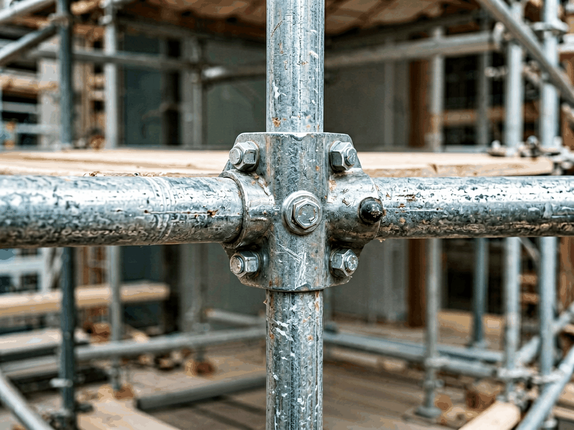
A fixed girder coupler is a rigid scaffolding component designed to securely connect two scaffold tubes at a precise 90-degree angle, forming a stable joint between vertical standards and horizontal ledgers or transoms. Unlike swivel couplers, which allow angular adjustment, fixed girder couplers maintain a permanent right-angle configuration, ensuring dimensional accuracy and load-path integrity in scaffold structures. These couplers are essential for creating load-bearing frameworks where geometric consistency directly impacts structural safety and resistance to lateral forces.
The coupler consists of two opposing jaws, each featuring a curved saddle that matches the outer diameter of standard scaffold tubes (typically 48.3 mm). High-strength steel bolts pass through threaded lugs on the jaws, applying clamping force to deform the saddles slightly around the tubes, creating friction-based resistance to slip. The fixed angular relationship between the jaws ensures that axial, shear, and moment loads are transferred predictably through the coupler body, minimizing eccentric loading on connected tubes. This design eliminates reliance on welds or pins at the joint, which could introduce stress concentrations or failure points under cyclic loading.
The coupler’s internal geometry is engineered to distribute clamping pressure evenly across the tube contact surface, reducing localized stress and preventing tube ovalization under high loads. Finite analysis shows that optimal jaw curvature and bolt placement achieve uniform pressure distribution, which enhances slip resistance compared to designs with sharp edges or uneven force paths. The rigid frame connecting the jaws resists twisting and spreading forces, maintaining the 90-degree angle even when subjected to off-axis loads common in dynamic construction environments.
Fixed girder couplers are typically manufactured from hot-rolled structural steel grades such as S275JR or S355JR, chosen for their balance of yield strength, ductility, and weldability. The material must withstand repeated elastic deformation during clamping cycles without permanent set or cracking. Minimum yield strength of 275 MPa ensures adequate resistance to bolt over-torque and tube slip, while elongation exceeding 20% provides toughness to absorb impact loads during handling or accidental impacts. Surface treatments like hot-dip galvanizing (minimum 55 µm zinc coating per EN ISO 1461) provide corrosion resistance suitable for outdoor use over multiple seasons.
Alternative materials include weathering steel (e.g., S355J2W) for reduced maintenance in low-pollution environments, or stainless steel (e.g., grade 1.4301) for applications requiring high corrosion resistance, such as chemical plants or marine scaffolding. However, carbon steel with galvanization remains the most economical choice for general construction due to its proven performance, recyclability, and compatibility with standard scaffolding systems. Material test certificates (EN 10204 3.1) are available upon request to verify chemical composition and mechanical properties.
These couplers are designed to interface with scaffold tubes conforming to EN 39 or equivalent national standards (e.g., BS 1139, ASTM A500), which specify an outer diameter of 48.3 mm and wall thicknesses ranging from 3.2 mm to 4.0 mm. The internal saddle dimensions are precision-machined to accommodate this tube size with a controlled interference fit, ensuring sufficient clamping force without requiring excessive bolt torque that could damage the tube or coupler threads. Deviations beyond ±0.5 mm in tube diameter may compromise slip resistance and should be avoided.
Compliance with performance standards such as EN 74-1 or BS 1139 Part 2 is verified through type testing, which includes static load tests to determine characteristic values for slip resistance and ultimate strength. Typical slip load values exceed 6.0 kN per coupler under standard test conditions, while ultimate tensile and shear capacities are significantly higher, providing ample safety margin for design loads specified in scaffolding codes like TG20:21 or AS/NZS 1576. Couplers are marked with manufacturer identification, standard reference, and batch number for traceability.
Fixed girder couplers are primarily used to connect horizontal ledgers or transoms to vertical standards in facade scaffolding, birdcage scaffolds, and independent tied scaffolds. Their fixed 90-degree angle ensures accurate positioning of horizontal members, which is critical for maintaining uniform bay dimensions, level working platforms, and proper alignment of diagonal bracing. In facade systems, they enable the creation of rigid grid structures that resist wind loads and provide stable support for bricklaying, plastering, or cladding operations.
In birdcage scaffolds used for soffit work or ceiling access, fixed girder couplers form the primary grid where ledgers connect to standards at right angles, creating a stable platform capable of supporting uniform distributed loads from workers, tools, and materials. They are also employed in stair tower assemblies to attach tread transoms to vertical standards, ensuring safe and level access routes. The rigidity of the joint minimizes platform deflection under load, improving worker safety and comfort during prolonged use.
Compared to swivel couplers, fixed girder couplers offer superior stiffness and predictable load transfer at right-angle joints, making them preferable for primary structural connections where angular accuracy is essential. Swivel couplers introduce rotational flexibility that can lead to joint movement under load, requiring additional bracing to maintain stability. However, swivel couplers are necessary for connecting tubes at non-standard angles, such as in ramps or irregular façades, where fixed couplers cannot be used.
Putlog couplers, which feature a flat bearing surface for supporting putlogs or bearers, are designed for lighter-duty applications and cannot resist significant moment loads. Fixed girder couplers, by contrast, are engineered to handle combined axial, shear, and bending forces, making them suitable for main structural joints. Sleeve couplers join tubes end-to-end for length extension but do not provide angular connection; they serve a different functional purpose and are not interchangeable with girder couplers in scaffold assembly.
Manufacturing begins with cutting and shaping steel plates or forgings to form the coupler jaws and connecting body. Critical dimensions—such as saddle radius, bolt hole spacing, and jaw parallelism—are maintained through precision tooling and regular gauge inspections. Each coupler undergoes proof load testing during production validation to verify clamping force and slip resistance, with statistical process control applied to monitor consistency. Weld-free designs are preferred to avoid heat-affected zone weaknesses, with components joined via high-strength bolts or forged as integral units where feasible.
Surface preparation before galvanizing includes degreasing, pickling, and fluxing to ensure zinc adhesion and coating uniformity. Post-galvanizing inspections check for coating thickness, adhesion, and freedom from defects such as bare spots or excessive roughness. Threaded components are gauged to prevent bolt seizure or cross-threading during assembly. Final visual and dimensional checks confirm markings are legible and components are free from burrs, sharp edges, or deformation that could impede safe handling or tube insertion.
Standard fixed girder couplers are supplied in galvanized finish for immediate use in most construction environments. Alternative finishes, such as powder coating in specific colors for identification or corrosion resistance in aggressive atmospheres, are available upon request. Custom branding or laser engraving of company logos and batch numbers can be applied for traceability and site management purposes. Minimum order quantities apply to non-standard finishes or markings.
While the core design is standardized to ensure compatibility with common scaffolding systems, minor adaptations—such as adjusted bolt lengths for non-standard tube thicknesses or modified jaw geometry for proprietary tube profiles—can be evaluated based on project requirements. Engineers should provide tube specifications, expected load conditions, and environmental factors when requesting quotations. Technical support is available to assess suitability for specialized applications, including temporary structures with unique geometric constraints.
| Parameter | Typical Value | Notes |
|---|---|---|
| Tube Compatibility | 48.3 mm OD | Matches EN 39 / BS 1139 scaffold tubes | Material | S275JR or S355JR steel | Hot-dip galvanized min. 55 µm coating |
| Slip Load Capacity | ≥ 6.0 kN | Per EN 74-1 test conditions |
| Bolt Size | M12 or M16 | Grade 8.8, torque-controlled tightening |
| Operating Temperature | -20°C to +50°C | Galvanized coating stability range |
| Weight (approx.) | 1.2–1.8 kg | Varies by design and material thickness |
Proper installation requires tightening bolts to the manufacturer’s specified torque using a calibrated wrench to achieve consistent clamping force. Under-torquing reduces slip resistance, while over-torquing risks thread stripping or tube deformation. Regular inspection during use should verify bolt tightness, absence of corrosion damage, and jaw alignment. Any coupler showing signs of cracking, excessive wear, or permanent deformation must be removed from service immediately, regardless of visible damage severity.
When stored, couplers should be kept in dry conditions to prevent white rust formation on galvanized surfaces. Stacking should avoid point loading that could deform jaws or threads. Before reuse, components must be cleaned and inspected for compliance with reuse criteria outlined in local scaffolding regulations. Documentation of inspection and maintenance activities supports audit trails and demonstrates due diligence in equipment management.





