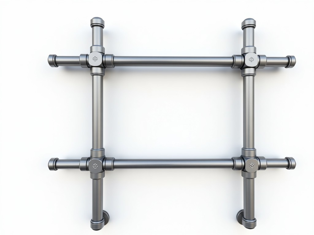
Extension ladder scaffolding brackets are engineered components designed to securely attach extension ladders to scaffold systems, creating stable elevated work platforms. They convert standard ladders into integrated access solutions for construction, maintenance, and industrial applications where temporary height access is required.
These brackets address the safety and efficiency challenges of using ladders independently on scaffolds by providing a fixed connection point that prevents lateral movement and reduces fall hazards. Their design focuses on load distribution, compatibility with common scaffold tube diameters, and ease of installation without specialized tools.
Extension ladder scaffolding brackets are typically fabricated from structural-grade steel or aluminum alloys selected for their strength-to-weight ratio and corrosion resistance. Steel brackets often use hot-dip galvanizing or powder coating for outdoor durability, while aluminum versions rely on natural oxide film resistance and may receive anodizing for enhanced surface hardness.
Key dimensional parameters include the scaffold tube clamp range (commonly 48–51 mm outer diameter to match standard scaffold tubing), ladder rail engagement width (accommodating 30–50 mm flange thicknesses), and vertical adjustment range (typically 100–200 mm to align with varying ladder rung spacings). Load ratings are determined through static testing, with most designs rated for 220 kg (485 lbs) concentrated load per bracket pair, compliant with EN 131-4 and ANSI/ASSE A14.2 standards for temporary access equipment.
The mechanical interface incorporates a dual-locking mechanism: a primary clamp secures the bracket to the scaffold tube via a threaded bolt and nut assembly, while a secondary retention system (often a spring-loaded pin or wedge lock) engages the ladder rail to prevent disengagement under vibrational loads. This two-stage locking reduces reliance on single-point failure and allows visual confirmation of secure engagement.
Bracket assemblies are engineered to withstand combined loads from user weight, tool carriage, and dynamic forces during ascent/descent. Finite analysis typically shows stress concentrations at the clamp bolt hole and ladder rail contact points, prompting design features like gussets, radiused transitions, and increased material thickness in these zones.
Safety factors are applied to ultimate tensile strength values, with working load limits set at 25% of material yield strength for steel and 33% for aluminum alloys, accounting for long-term creep, fatigue from repeated loading, and environmental degradation. Deflection under rated load is limited to less than 3 mm to ensure ladder stability and user confidence.
Corrosion allowance is considered in material selection; for instance, galvanized steel brackets maintain structural integrity for 5+ years in C3 environments per ISO 12944, while marine-grade aluminum alloys (e.g., 5083-H111) are specified for coastal or chemical exposure scenarios. Regular inspection focuses on clamp bolt torque, wear on engagement surfaces, and coating integrity.
In façade renovation projects, extension ladder scaffolding brackets enable workers to access elevated surfaces without erecting full scaffold bays, reducing material handling and setup time. The bracket allows the ladder to follow the contour of the building, maintaining consistent working height while moving horizontally—a critical advantage over fixed ladder systems on irregular substrates.
For industrial plant maintenance, these brackets provide temporary access to piping, ductwork, and equipment mounted at height on existing scaffold structures. Unlike standalone ladders, which require repositioning and pose slip risks on uneven surfaces, bracketed systems remain fixed relative to the scaffold, allowing both hands free for tool operation and improving task efficiency.
In shipbuilding and offshore environments, corrosion-resistant aluminum brackets are used with ladders to access hull sections, tank interiors, and superstructure components during fabrication or repair. Their non-magnetic properties (in non-ferrous alloys) prevent interference with sensitive instrumentation, and low mass reduces crane load during module lifting operations.
Fixed-offset brackets position the ladder at a set distance from the scaffold face (typically 150–250 mm), ideal for uniform surfaces where consistent clearance is needed. Adjustable-offset models use sliding mechanisms or multiple bolt holes to vary the ladder-to-scaffold distance, accommodating protrusions like conduit, insulation, or uneven cladding.
Some designs incorporate swivel heads that allow the ladder to angle away from the scaffold, useful for working overhangs or accessing confined spaces behind obstacles. Quick-release variants feature tool-free levers or eccentric cams for rapid installation and removal, beneficial in short-duration tasks where ladder repositioning occurs frequently.
Customization options include ladder rail profile matching (for I-beam, C-channel, or rectangular tube ladders), scaffold tube size adaptation (for 42 mm, 48.3 mm, or 60.3 mm systems), and integration with guardrail systems. Specialty coatings such as zinc-nickel plating or marine-grade epoxy are available upon request for extreme environments.
Production begins with certified raw materials—steel coils meeting EN 10025-2 S275JR or aluminum ingots per EN 573-3—accompanied by mill test certificates. Critical dimensions are verified using CNC machining or precision stamping dies, with first-article inspection comparing physical samples to 3D CAD models and tolerance stacks.
Welded assemblies (if applicable) undergo visual inspection per EN ISO 5817 and dye penetrant testing for surface-breaking flaws. Load testing is performed on sample batches using calibrated hydraulic rams to validate ultimate strength and deflection characteristics, with results documented in batch-specific test reports.
Surface treatments are monitored for thickness and adhesion; galvanized coatings are measured via magnetic induction probes, while powder coating thickness is verified using ultrasonic gauges. Final assembly includes functional testing of locking mechanisms and torque verification of clamp bolts to specified values (typically 25–35 Nm for M12 hardware).
| Parameter | Typical Value | Notes |
|---|---|---|
| Scaffold Tube Clamp Range | 48–51 mm OD | Matches standard scaffold tubing |
| Ladder Rail Engagement | 30–50 mm flange width | Accommodates common ladder profiles |
| Vertical Adjustment Range | 100–200 mm | Aligns with rung spacings |
| Working Load Limit (Pair) | 220 kg (485 lbs) | Static load, safety factor applied |
| Max Deflection at Load | < 3 mm | Ensures ladder stability |
| Clamp Bolt Torque | 25–35 Nm | For M12 hardware, steel |
| Material Options | S275JR Steel, 6061-T6 Al | Galvanized or anodized finish |
| Corrosion Resistance | C3/C4 (Steel), Marine (Al) | Per ISO 12944 / ASTM B117 |
Correct installation begins with verifying scaffold tube diameter and ladder rail dimensions against bracket specifications. The clamp assembly is opened, positioned over the scaffold tube, and secured by tightening the bolt to the manufacturer’s specified torque—under-torquing risks slippage, while over-torquing can deform the tube or strip threads.
The ladder is then lifted into the bracket’s engagement slots, ensuring the retention pin or wedge fully seats into the rail hole or flange. A visual and tactile check confirms no movement; any play indicates incomplete engagement. Users should apply downward force on the ladder to seat it fully before applying lateral loads.
Periodic inspection during use includes checking clamp bolt torque (especially after initial loading), examining engagement surfaces for wear or deformation, and verifying coating integrity. Brackets showing cracks, permanent deformation, or excessive corrosion must be removed from service immediately. Storage in dry conditions prevents premature degradation.
Materials are selected to meet RoHS and REACH requirements where applicable, avoiding hazardous substances like lead, cadmium, or hexavalent chromium in coatings. Trivalent chromium passivation is commonly used for zinc-plated steel as an environmentally preferable alternative to hexavalent chromium processes.
While not classified as personal protective equipment (PPE), these brackets contribute to fall protection systems when used as part of a compliant access solution. Their role is to provide secure ladder positioning, complementing other safety measures such as harnesses, guardrails, and proper scaffold erection per local regulations (e.g., OSHA 1926 Subpart L, EU Directive 2001/45/EC).
Manufacturers typically provide declaration of conformity documents referencing relevant standards (EN 131-4, ANSI/ASSE A14.2) rather than issuing certifications, as the final safety of the assembled system depends on correct installation, ladder condition, and scaffold integrity—factors outside the bracket manufacturer’s direct control.
For projects requiring traceability, brackets can be laser-etched or stamped with batch numbers, material codes, and load ratings. This supports inspection regimes and incident investigations. Packaging is designed to prevent damage during transit, with brackets often packed in corrosion-inhibiting cartons or reusable steel racks for bulk orders.





