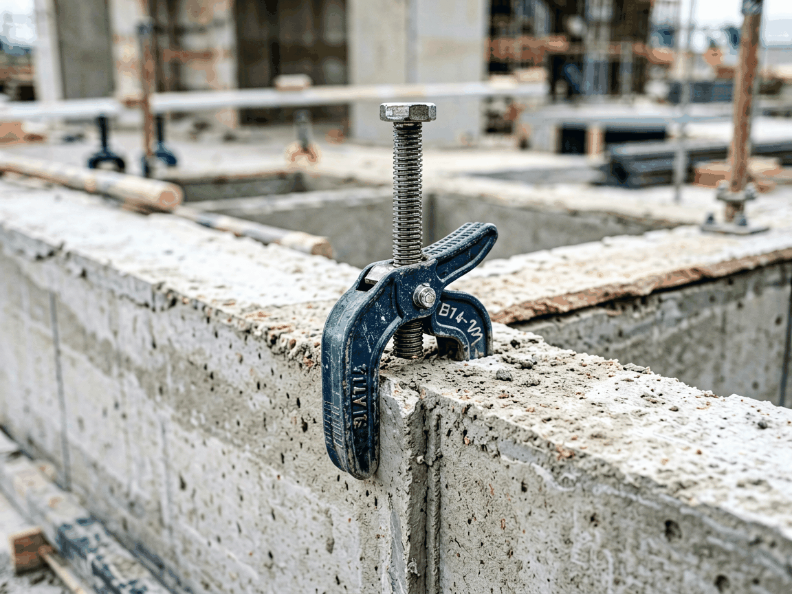
The Doka clamp for formwork masonry is a purpose-built fastening system designed to securely connect formwork panels to masonry substrates during concrete placement. Unlike generic clamps, it addresses the specific challenges of masonry interfaces, where surface irregularities, varying compressive strength, and limited anchorage depth require a clamping mechanism that adapts without damaging the substrate or compromising alignment tolerance.
Engineered for repeatable use in high-cycle construction environments, the clamp transfers lateral formwork loads directly into the masonry through a controlled bearing interface, minimizing slippage and maintaining dimensional accuracy of the formed concrete edge. Its design prioritizes quick installation and removal while maintaining consistent clamping force across multiple pour cycles.
The clamp body is manufactured from forged steel grade S355J2, selected for its yield strength of 355 MPa and toughness at low temperatures, ensuring resistance to deformation under cyclic loading. The clamping arm features a hardened steel insert (HRC 58-62) at the contact point with the formwork profile, reducing wear during frequent adjustments. All load-bearing surfaces are machined to a flatness tolerance of 0.1 mm to ensure even pressure distribution.
The clamping force is generated via a threaded spindle with trapezoidal thread (Tr 20x4), allowing precise adjustment through a 22 mm hex drive. One full rotation translates to 4 mm of linear movement, enabling fine-tuning of formwork position. The spindle is coated with a dry film lubricant (MoS₂-based) to maintain consistent torque-to-force conversion over 500+ cycles without galling.
The masonry interface uses a replaceable neoprene pad (Shore A 65) bonded to a steel backing plate, conforming to surface irregularities up to 3 mm depth while distributing pressure to prevent local crushing of brick or block. The pad is recessed within a steel housing to prevent extrusion under load and is designed for tool-free replacement when worn.
The clamp is rated for a safe working load (SWL) of 15 kN per unit when installed in masonry with a minimum compressive strength of 10 N/mm² (C10/15). This rating is derived from finite element analysis validated by physical testing on clay brick and concrete block substrates, incorporating a safety factor of 3:1 against slip failure under static load.
Under dynamic loading conditions simulating vibration from concrete pumping, the clamp maintains positional stability within ±1.5 mm when spaced at 600 mm intervals along the formwork edge. Testing shows no measurable settling after 10 consecutive pour cycles when re-torqued to 80 Nm prior to each use.
The maximum allowable tightening torque is 100 Nm, beyond which the spindle threads may experience permanent deformation. A torque wrench is recommended for installation to ensure consistent preload across all clamps in a system. The clamp’s self-locking thread design prevents loosening under vibration without requiring lock nuts or secondary locking mechanisms.
The Doka clamp for formwork masonry is designed to interface with Doka’s top rail and side rail profiles used in wall formwork systems such as Dokamatic and Framax. The clamping jaw accommodates flange thicknesses from 8 mm to 16 mm and web heights up to 120 mm, covering the standard range of Doka aluminum and steel formwork beams.
For non-Doka formwork, adaptation plates are available to convert the clamp’s interface to accommodate alternative beam geometries, such as I-sections or custom extrusions. These plates are machined to match the clamp’s mounting pattern and are secured with two M12 socket head cap screws. Compatibility must be verified per project based on formwork moment of inertia and deflection limits.
The clamp is not intended for use with timber formwork or thin-gauge steel profiles lacking sufficient flange rigidity, as concentrated point loads may cause local buckling. In such cases, a load-spreading washer or continuous backing bar is required, which should be specified during formwork design.
Installation begins with drilling a 14 mm diameter hole into the masonry substrate at the specified formwork offset, typically 50–100 mm from the edge of the concrete pour. The hole depth should be at least 60 mm to ensure adequate embedment of the steel backing plate. After hole cleaning, the clamp is positioned and the spindle tightened to 80 Nm using a calibrated torque wrench.
Clamps should be spaced at intervals not exceeding 800 mm for standard wall formwork, reduced to 600 mm when pouring high-slump concrete (>160 mm) or when the formwork span exceeds 2.5 m between ties. Corner conditions require additional clamps within 150 mm of the intersection to prevent rotation. All clamps must be inspected for pad wear and spindle thread condition before each reuse cycle.
Removal is performed by reversing the spindle rotation; the neoprene pad typically releases without adhesion to the masonry. Any residual debris should be brushed from the clamp body, and the spindle thread inspected for galling or debris accumulation. Lubrication of the thread is not required between uses due to the dry film coating, but visual inspection for coating integrity is recommended every 50 cycles.
The standard clamp is available in two configurations: one for vertical masonry surfaces (wall applications) and another adapted for soffit or underside-of-slab formwork where the load direction is tensile. The soffit version includes a safety pin to prevent accidental disengagement under uplift forces and is rated for 10 kN SWL under the same substrate conditions.
Surface treatments include standard black oxide coating for corrosion resistance in mild environments and optional hot-dip galvanizing (Zn-min 55 µm) for prolonged exposure to moisture or alkaline concrete wash water. Stainless steel variants (grade 1.4404 / AISI 316L) are available upon request for chloride-exposed environments, such as marine structures or wastewater treatment plants, with equivalent mechanical properties to the carbon steel base.
Custom spindle lengths are offered to accommodate varying formwork offsets or insulation layers between the masonry and formwork, ranging from standard 75 mm to 150 mm in 25 mm increments. Non-standard thread pitches or left-hand threads are available for specialized applications but require engineering review to ensure self-locking behavior under load.
Each clamp undergoes dimensional verification of critical features—spindle thread pitch, jaw opening, and pad recess depth—using calibrated gauges before surface treatment. Material traceability is maintained from ingot to finished part, with mill certificates available for the forged steel body and spindle upon request.
Load testing is performed on a sampling basis using hydraulic actuators to confirm static slip resistance and cyclic durability. Functional testing includes 500 tightening-loosening cycles to verify spindle integrity and thread coating adhesion. Visual inspection criteria include absence of cracks, folds, or surface imperfections in load paths, assessed under 10x magnification.
The manufacturing process follows ISO 9001:2015 principles, with process controls for forging temperature, machining tolerances, and heat treatment consistency. Final assembly includes torque verification of the spindle nut to ensure proper preload retention. Documentation of conformance is provided with each batch shipment.
| Parameter | Typical Value | Notes |
|---|---|---|
| Safe Working Load (SWL) | 15 kN | Per clamp, in masonry ≥10 N/mm², static load |
| Clamping Force Range | 10–25 kN | Adjustable via spindle torque (40–100 Nm) |
| Spindle Thread | Tr 20x4 (trapezoidal) | Self-locking, dry film lubricated |
| Masonry Interface Pad | Neoprene, Shore A 65 | Replaceable, 3 mm conformability |
| Max Tightening Torque | 100 Nm | Beyond this, thread deformation risk |
| Recommended Spacing | 600–800 mm | Depending on concrete pressure and span |
| Material (Standard) | Forged S355J2 steel | Yield strength 355 MPa |
| Surface Treatment | Black oxide or HDG | Stainless steel optional |
For project-specific inquiries, including load calculations for unique formwork geometries, adaptation to non-standard masonry types, or certification requirements for regulated industries, contact our technical team. Provide details such as formwork load data, substrate compressive strength, pour height, and concrete slump to enable accurate clamping system design.
Samples are available for evaluation upon request, subject to availability and project lead time. Technical documentation, including installation manuals, load tables, and material certificates, can be shared after preliminary project review. Lead time for standard configurations is typically 3–4 weeks; customized variants may require additional time for tooling and validation.
To discuss your formwork masonry clamping needs or request a quotation, visit our contact page. Our engineers will review your specifications and recommend a clamping solution aligned with your project’s safety, schedule, and budget constraints.
Request Technical Consultation




