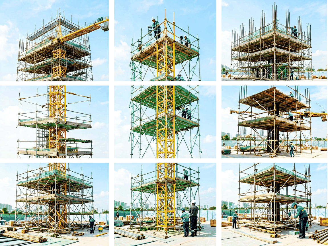
A scaffolding system is not a single component but an assembly of interdependent parts, each engineered to perform a specific structural function. Understanding these parts is essential for safe assembly, load distribution, and compliance with temporary works standards such as EN 12810/12811 or OSHA 1926 Subpart L. This page explains the core components, their material characteristics, dimensional roles, and how they interact to form a stable, load-bearing framework.
Standards are the vertical tubes that transfer the entire load from the working platform down to the base or ground. They are typically manufactured from hot-dip galvanized steel with an outer diameter of 48.3 mm and wall thicknesses ranging from 3.2 mm to 4.0 mm, depending on load class. The tube ends feature forged or pressed couplings—often pin-and-socket or wedge-lock types—that enable vertical stacking without loss of alignment. Standards are spaced according to bay length (commonly 1.8 m, 2.5 m, or 3.0 m) and must remain plumb within ±1.5° to prevent eccentric loading.
Ledgers run horizontally between standards, providing lateral stability and supporting the transoms or putlogs that carry the working platform. They are usually the same diameter and wall thickness as standards but feature end fittings designed to clamp securely to the standard’s coupling system. Ledger length defines the bay width—common sizes include 0.9 m, 1.2 m, 1.5 m, and 1.8 m—and must resist bending moments from platform loads and wind forces. Connection stiffness is critical; slip-resistant couplings ensure minimal movement under cyclic loading.
Transoms are horizontal members placed perpendicular to ledgers, directly supporting scaffold boards or decking systems. Putlogs are similar but have one end flattened or bent to rest on a building structure (e.g., a wall), while the other end connects to a ledger. Both are typically made from 48.3 mm × 3.2 mm steel tube, with transoms spaced no more than 1.2 m apart for standard timber boards and 0.6 m for thinner decking materials. Their primary function is to distribute point loads from workers and materials evenly across the ledger system, preventing localized deformation or board failure.
Base plates distribute the load from the standard’s bottom end onto the sole board or ground surface, reducing ground pressure and preventing sinking. A typical base plate is 150 mm × 150 mm × 6 mm steel, welded to a spigot that fits into the standard’s hollow tube. Sole boards—usually 250 mm wide, 35 mm thick, and pressure-treated timber—spread the load over a larger area, especially on soft or uneven ground. On hard surfaces like concrete, base plates may be used alone; on soil or gravel, sole boards are mandatory to meet bearing capacity requirements (typically < 100 kPa for compacted fill).
Braces prevent racking and sway by transferring lateral forces—such as wind, impact, or uneven loading—into the vertical plane. Diagonal braces connect standards in a zigzag pattern across bays, forming rigid triangles that resist deformation. Plan braces run horizontally at the base or mid-height to lock the scaffold’s footprint against lateral shift. Both are typically made from the same tube as standards and ledgers, connected via swivel couplers that allow angle adjustment. Bracing frequency depends on height: every third bay for structures under 10 m, every second bay above that, per EN 12811-1 guidelines.
Couplers are the critical joints that join tubes at specific angles—right-angle, swivel, or parallel—without welding. They are forged from malleable iron or ductile steel, hot-dip galvanized, and designed to slip over 48.3 mm tubes with a controlled interference fit. Tightening is achieved via bolts (usually M16 or M20) torqued to 50–70 Nm to prevent slippage under load. Swivel couplers allow variable angles for irregular geometries, while right-angle couplers ensure 90° joints for ledger-to-standard connections. Coupler strength must exceed the tube’s yield strength to avoid joint failure before tube buckling.
Guardrails and toeboards are safety components, not load-bearing, but essential for fall protection. Guardrails consist of a top rail (minimum 950 mm above platform) and mid-rail, both typically 48.3 mm × 3.2 mm tube, installed along open sides and ends of platforms. Toeboards—minimum 150 mm high—are fitted along the platform edge to prevent tools or materials from falling. They are attached via specialized clips or brackets that clamp to standards or ledgers without damaging the tube surface. These components must withstand a horizontal force of 200 N applied at any point without permanent deformation, per EN 13374 Class A.
The working platform is formed by scaffold boards or modular decking panels laid across transoms. Traditional boards are solid spruce or pine, 225 mm wide, 38 mm thick, and up to 3.0 m long, graded for strength (e.g., C24 timber) and inspected for knots, splits, or rot. Modular alternatives include steel decking panels with perforated surfaces for drainage or aluminum frames with plywood infill, offering reusable, non-absorbent surfaces. Board overhang beyond the transom should be 50 mm minimum and 150 mm maximum to prevent tipping. Deflection under uniform load must not exceed span/200 to maintain safe working conditions.
All primary structural tubes are made from S355JO hot-rolled steel, selected for its balance of yield strength (min 355 MPa) and ductility, which allows deformation before fracture under overload. Hot-dip galvanizing (minimum 55 μm zinc coating per EN ISO 1461) provides corrosion resistance for outdoor use, with maintenance intervals typically 5–7 years in industrial environments. Threaded components like coupler bolts use grade 8.8 steel, zinc-plated, and are designed for reuse—thread integrity is inspected after each cycle. Aluminum scaffolding uses 6061-T6 alloy tubes (diameter 48.3 mm, wall 3.0 mm) for lightweight applications where manual handling is frequent, though load capacity is lower than steel equivalents.
| Component | Typical Material | Key Dimensional Parameter | Primary Function |
|---|---|---|---|
| Standard | S355JO Steel, HDG | 48.3 mm OD × 3.2–4.0 mm WT | Vertical load transfer |
| Ledger | S355JO Steel, HDG | 48.3 mm OD × 3.2 mm WT | Horizontal stability, platform support |
| Transom | S355JO Steel, HDG | 48.3 mm OD × 3.2 mm WT | Board support, load distribution |
| Base Plate | S235JR Steel, HDG | 150 mm × 150 mm × 6 mm | Load spreading to sole/ground |
| Coupler (Right-Angle) | Malleable Iron, HDG | Fits 48.3 mm tube | Secure 90° joint |
| Guardrail | S355JO Steel, HDG | 48.3 mm OD × 3.2 mm WT | Fall protection (top/mid rail) |
| Scaffold Board | C24 Spruce/Pine | 225 mm × 38 mm × ≤3.0 m | Working surface |
Scaffolding systems are designed for interoperability within the same manufacturer’s coupling standard—mixing tube diameters or coupler types from different brands risks joint slippage or misalignment. Always verify that standards, ledgers, and transoms share the same outer diameter (48.3 mm is near-universal) and that couplers are rated for the same tube wall thickness. Bay dimensions must align with board lengths to avoid excessive overhang or gaps. Before use, a competent person must inspect all components for damage: bends >5°, corrosion exceeding 10% wall loss, cracked welds, or deformed couplers require removal from service. Documentation of inspection dates and maintenance history is required under most regional safety regulations.





