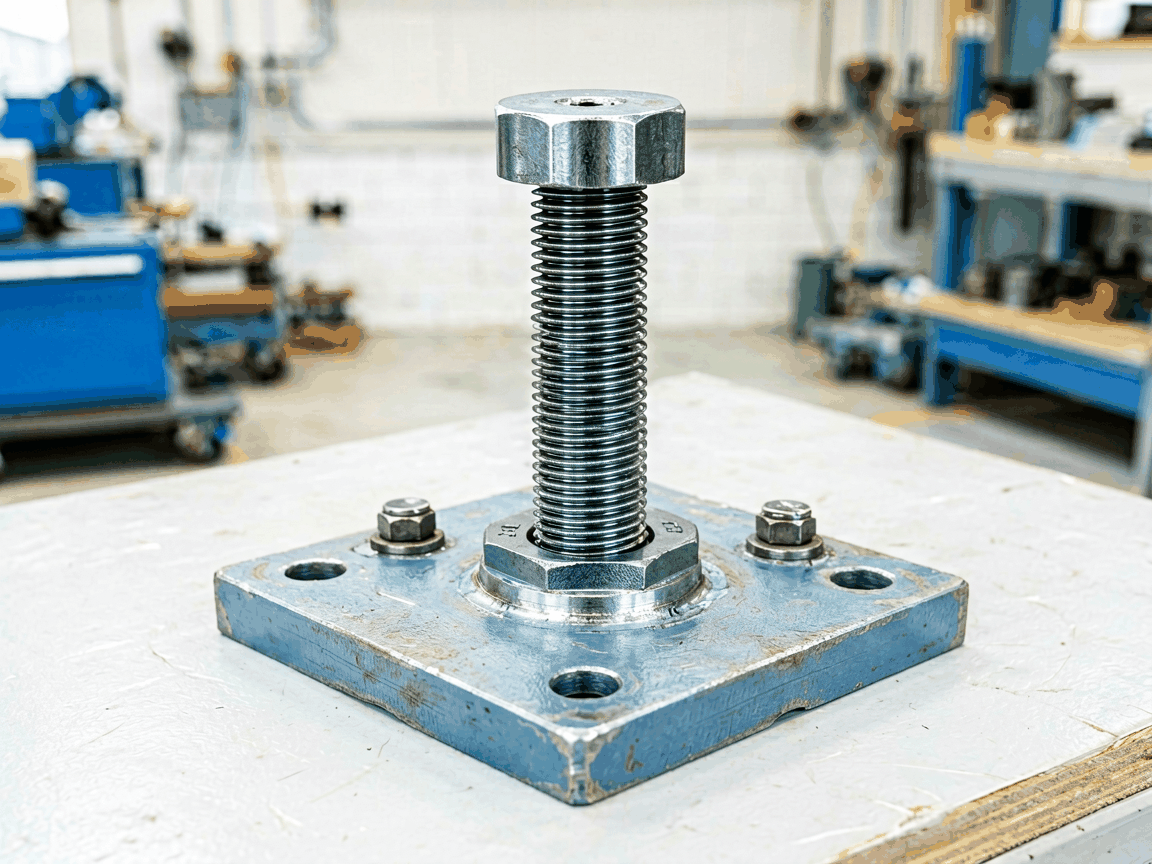
The base plate assembly is a critical structural interface in screw jack systems, responsible for transferring axial loads from the lifting mechanism to the foundation while maintaining alignment and stability under dynamic conditions. Proper design ensures even load distribution, minimizes settlement, and prevents localized stress concentrations that could compromise system integrity over time.
In industrial applications such as material handling, stage machinery, and precision positioning systems, the base plate must accommodate both static and dynamic loads while resisting lateral displacement. Material selection, thickness, and mounting hole configuration directly influence long-term performance, especially in environments subject to vibration or cyclic loading.
Base plate assemblies are engineered to match the screw jack’s load capacity and mounting geometry. Thickness typically ranges from 20 mm to 50 mm for carbon steel variants, increasing with load rating to limit deflection under maximum service load. Hole patterns conform to ISO or manufacturer-specific standards to ensure compatibility with mating components.
Surface flatness is controlled to within 0.1 mm over a 300 mm span to prevent binding or uneven load transfer. Edge breaks and chamfers are standardized to reduce stress risers and facilitate safe handling during installation. Welded reinforcements, where used, are sized to match the base material thickness and are fully penetrated to avoid fatigue initiation points.
Common base materials include S235JR, S355JR, and C45 carbon steel, selected based on required yield strength and weldability. For corrosive environments, hot-dip galvanizing (minimum 60 μm zinc coating) or epoxy powder coating (80–120 μm thickness) is applied to extend service life. Stainless steel grades 304 and 316 are available for hygienic or marine applications where contamination resistance is critical.
Hardened wear plates or bronze inserts may be integrated into high-cycle applications to reduce fretting wear at the jack interface. All materials are supplied with mill test certificates traceable to the heat number, enabling full material validation during quality audits.
Standard base plate diameters range from 120 mm to 300 mm, corresponding to screw jack capacities from 5 kN to 250 kN. Custom sizes are available upon request, with rectangular or oblong variants designed for specific machine foundations or space-constrained installations.
Mounting holes are typically M16 to M30, spaced according to the jack’s flange pattern, with tolerances held to ±0.5 mm for positional accuracy. Counterbores for socket head cap screws are standard to allow flush mounting and prevent protrusion-related interference.
| Parameter | Typical Range | Notes |
|---|---|---|
| Base Plate Thickness | 20–50 mm | Increases with load capacity |
| Diameter (Round) | 120–300 mm | Custom shapes available |
| Mounting Hole Size | M16–M30 | Per jack flange pattern |
| Surface Flatness | ≤0.1 mm/300 mm | Measured across plate |
| Coating Thickness (Zn) | ≥60 μm | Hot-dip galvanized |
In automated warehousing systems, screw jack base plates are anchored to reinforced concrete floors to support vertical lift modules handling palletized goods. The assembly must resist overturning moments caused by off-center loading during acceleration and deceleration cycles.
For theater and stage machinery, base plates are designed with low profiles and vibration-damping interfaces to minimize transmission of operational noise to the substructure. Precise alignment ensures smooth movement of scenic elements without binding or jerking.
In precision manufacturing equipment such as CNC press brakes or coordinate measuring machines, the base plate contributes to overall system rigidity. Any compliance at the interface can introduce positioning errors, making flatness and stiffness critical parameters.
Each base plate assembly undergoes dimensional verification using coordinate measuring machines (CMM) to confirm hole positions, diameters, and flatness within specified tolerances. Visual inspection checks for surface defects, weld continuity, and coating uniformity per ISO 8501-1 standards.
Material hardness is tested at critical zones to ensure conformance with specified grades, particularly when heat treatment is applied. For coated units, adhesion and thickness are verified using destructive and non-destructive methods before shipment. All test results are retained for traceability.
Final assembly includes a trial fit with the corresponding screw jack to validate concentricity and rotational freedom. Any interference or binding is investigated and corrected prior to packaging. This functional check reduces field installation risks.
Customizations include non-standard hole patterns, oversized plates for special foundations, integrated leveling studs, or machined recesses for hydraulic or pneumatic actuators. Clients must provide load data, mounting interface drawings, and environmental conditions for accurate quotation.
Lead times typically range from 3 to 6 weeks depending on material availability and coating requirements. Samples or first-article inspection reports are available upon request for validation before full production release. Export packaging includes corrosion-inhibiting vapors and moisture barriers for long-term transit protection.





