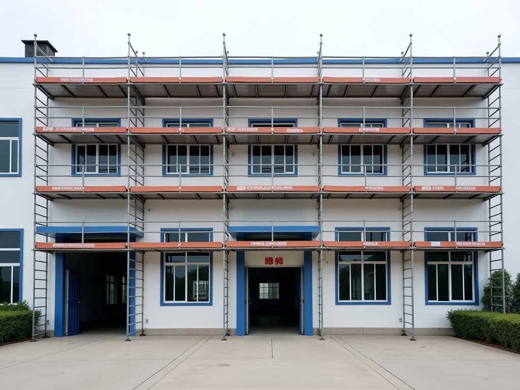
Scaffolding systems rely on standardized components to ensure structural integrity, load distribution, and worker safety across construction sites. The main parts — including vertical standards, horizontal ledgers, diagonal braces, base plates, and couplers — must meet strict dimensional tolerances and material specifications to perform reliably under dynamic loads. A factory specializing in these components focuses on precision manufacturing, material traceability, and compliance with international standards such as EN 74, BS 1139, or ANSI/ASSE A10.8. Understanding the function and engineering requirements of each part is essential for procurement decisions that impact site safety and project timelines.
Vertical standards, also known as uprights or posts, carry the primary axial load from the working platform down to the foundation. They are typically manufactured from cold-formed steel tubing with external diameters of 48.3 mm and wall thicknesses ranging from 2.7 mm to 3.2 mm, depending on load class. The tubing features perforations or pressed lugs at 50 mm or 100 mm intervals to enable secure coupling with horizontal members. Dimensional consistency in tube straightness, lug alignment, and wall thickness variation (<±0.15 mm) is critical to prevent eccentric loading and joint slippage under cyclic stress.
Horizontal ledgers and transoms connect between standards to form the scaffold frame and support decking materials. Ledgers run parallel to the building face and resist outward forces, while transoms span across the width to carry planks or panels. Both are made from the same 48.3 mm diameter tubing as standards, with forged or pressed end fittings that match the lug pattern on the standards. The end connections must maintain angular precision (±1°) and shear strength to resist racking forces. Welding procedures for lug attachment are qualified to ensure tensile strength exceeds 400 MPa in the heat-affected zone, preventing brittle failure under impact.
Diagonal braces provide lateral stability by preventing sway and twisting of the scaffold structure under wind or live loads. They are typically installed at a 45° to 60° angle between standards and connect via swivel couplers or fixed end fittings. Braces use the same tubing diameter but may incorporate adjustable telescoping sections to accommodate varying bay lengths. The buckling resistance of braces is calculated based on effective length and end fixity; factories ensure straightness tolerances of <0.5% of length and consistent end preparation to maintain design buckling capacity. Surface preparation before coating is controlled to avoid stress risers that could initiate fatigue cracks.
Couplers are the critical interface between scaffold tubes, transferring shear, tensile, and compressive forces while allowing rotational flexibility during assembly. Right-angle couplers connect ledgers or transoms to standards at 90°, while swivel couplers enable angular connections for bracing or irregular geometries. The coupler body is typically forged from malleable iron or ductile iron (grades equivalent to EN-GJS-400-15 or ASTM A536 60-40-18), providing a balance of strength, ductility, and wear resistance. The internal jaws must achieve full contact with the tube surface over at least 75% of the gripping length to prevent localized deformation and slip.
The tightening mechanism — usually a bolt and nut assembly — applies clamping force to generate friction between the tube and coupler jaws. Required torque values typically range from 50 to 70 Nm for standard couplers, producing a clamping force sufficient to resist slip under design loads (often 6.2 kN per coupler in tension and shear). Factories monitor bolt thread integrity, nut proof load, and washer hardness to ensure consistent preload. Regular sampling verifies that the coefficient of friction at the tube-coupler interface remains within the design range (0.15–0.25) after surface treatment, preventing under- or over-torquing risks.
Base plates and adjustable jack bases transfer the scaffold load from the standards to the ground or substructure while allowing for leveling on uneven surfaces. A standard base plate is typically 150 mm × 150 mm × 6 mm steel, welded or forged to the bottom of the standard with full penetration to ensure load distribution. The plate’s thickness and contact area are designed to limit ground pressure to acceptable levels (e.g., <150 kPa on compacted soil or <500 kPa on concrete). Adjustable bases incorporate a threaded spindle (typically Acme or trapezoidal thread) within a hollow collar, enabling vertical adjustment of up to 300 mm while maintaining load-bearing capacity.
The spindle must resist bending and buckling under combined axial and lateral loads; factories specify minimum core diameter and thread engagement length to prevent stripping or deformation. Nut locks or pin mechanisms prevent unintended rotation during use. Material selection for spindles and nuts often uses medium carbon steel (e.g., C45 or 1045 equivalent) hardened to HRC 22–28 for wear resistance without sacrificing toughness. Surface treatments such as hot-dip galvanizing (minimum 55 µm zinc coating) or electroplating are applied uniformly to prevent corrosion at load-bearing interfaces, with coating thickness verified via magnetic induction or gravimetric testing.
Tube material for standards, ledgers, and braces is predominantly hot-rolled or cold-formed carbon steel, with grades such as Q195, Q235, or S235JR being common due to their balance of yield strength (≥235 MPa), ductility, and weldability. Chemical composition is controlled to ensure consistent mechanical properties — particularly carbon content (<0.25%) and manganese content (0.3–0.6%) — to avoid brittleness or poor weldability. Factories conduct incoming material inspection via mill certificates and spot testing (tensile, yield, elongation) to verify compliance before processing. Tube straightness, ovality (<1%), and wall thickness uniformity are monitored during production using laser gauges and calipers.
For couplers and fittings, malleable iron or ductile iron castings are preferred for their ability to withstand repeated assembly cycles without cracking. The casting process is controlled to minimize porosity and shrinkage defects, with heat treatment (annealing or normalizing) applied to relieve internal stresses and improve machinability. Dimensional accuracy of critical features — such as jaw width, bolt hole position, and internal taper — is maintained within ±0.3 mm to ensure interchangeability and proper thread engagement. Surface preparation before coating includes shot blasting to Sa 2.5 standard to ensure adhesion and prevent coating delamination under cyclic loading.
Quality assurance begins with material traceability and extends through dimensional inspection, mechanical testing, and surface evaluation. Each batch of tubes undergoes tensile testing to confirm yield and tensile strength, elongation (>20%), and bendability without cracking. Couplers are proof-tested to 1.5 times the working load limit (WLL) in tension, shear, and torque to validate joint integrity. Non-destructive methods such as magnetic particle inspection may be used on critical welds or forgings to detect surface-breaking defects. Dimensional checks include go/no-go gauges for lug spacing, tube diameter, and coupler internal dimensions to ensure compatibility across production lots.
Surface treatment quality is verified through coating thickness measurements (minimum 55 µm for hot-dip galvanizing), adhesion tests (cross-hatch per ASTM D3359), and corrosion resistance testing (neutral salt spray per ISO 9227, typically 48–72 hours for initial assessment). Factories maintain inspection records for raw materials, in-process checks, and final product validation, enabling traceability from mill test certificate to shipped item. Sampling plans follow ISO 2859-1 standards, with acceptance criteria based on critical defect classification (e.g., dimensional non-conformance, missing lugs, inadequate torque resistance).
| Component | Typical Material | Key Dimensions | Surface Treatment |
|---|---|---|---|
| Vertical Standard | Q235 Steel Tube | 48.3 mm OD × 2.7–3.2 mm Wall | Hot-Dip Galvanized (55 µm min) |
| Horizontal Ledger | Q235 Steel Tube | 48.3 mm OD × 2.7–3.2 mm Wall | Hot-Dip Galvanized (55 µm min) |
| Diagonal Brace | Q235 Steel Tube | 48.3 mm OD × 2.7–3.2 mm Wall | Hot-Dip Galvanized (55 µm min) |
| Right-Angle Coupler | Malleable Iron (GTW-40-05) | Internal Jaw: 48.3–49.0 mm | Hot-Dip Galvanized or Painted |
| Base Plate | Q235 Steel | 150 mm × 150 mm × 6 mm | Hot-Dip Galvanized (55 µm min) |
| Adjustable Jack Base | C45 Spindle + Q235 Collar | Spindle: Ø26 mm, Thread: TR20×4 | Hot-Dip Galvanized (55 µm min) |
Note: Values represent typical configurations for standard duty scaffolding systems. Actual specifications may vary based on load class (e.g., Light, Medium, Heavy Duty per EN 12810-1), regional standards, or project-specific requirements. Custom lengths, tube thicknesses, or coupling types are available upon request, subject to engineering validation and minimum order quantities. All components are designed for interchangeability within standardized systems, but mixing parts from different manufacturers should be avoided unless compatibility is verified through physical testing or certified adapter use.
The main parts of scaffolding are used in a wide range of applications where temporary elevated work platforms are required. In building construction, they support formwork for concrete pouring, facade work such as cladding or window installation, and renovation projects involving brick repointing or roof repairs. The modular nature of tube-and-coupler systems allows adaptation to complex geometries, including curved structures, cantilevers, and suspended scaffolds, where standardized frames may not fit. In industrial maintenance, scaffolding provides access to towers, tanks, and process equipment in refineries, power plants, and manufacturing facilities, often requiring corrosion-resistant configurations for harsh environments.
Beyond construction, these components are utilized in event staging for concerts, exhibitions, and sports venues, where rapid assembly and disassembly are critical, and load requirements include dynamic forces from crowds or equipment. In shipbuilding and offshore industries, scaffolding supports hull inspection, painting, and welding operations, necessitating higher resistance to saltwater exposure and impact loads. The ability to fabricate custom lengths, bent components, or specialized couplers enables use in confined spaces or non-standard geometries, such as inside boilers, silos, or underground shafts, where access is limited and safety margins are reduced.
While standard components meet the needs of most projects, certain applications require modifications to length, end configuration, or material properties. Custom tube lengths are commonly requested to reduce on-site cutting and welding, improving efficiency and maintaining coating integrity. For example, standards may be cut to exact floor-to-ceiling heights in interior fit-outs, or ledgers tailored to specific bay widths in renovation projects to avoid splicing. End modifications — such as swivel ends, fork heads, or base collars — enable connection to structural steel, concrete inserts, or suspended systems, expanding the scaffold’s utility beyond simple independent towers.
Material substitutions may be specified for environments with elevated corrosion risks, such as coastal areas, chemical plants, or wastewater treatment facilities. Options include hot-dip galvanizing with increased coating thickness (80–100 µm), galvannealing for paint adhesion, or use of weathering steel (Corten A equivalent) in low-maintenance applications. In projects requiring non-sparking tools — such as oil and gas facilities — bronze or aluminum alloy couplers may be considered, though these require careful load assessment due to lower strength and different wear characteristics. All customizations are subject to engineering review to ensure load capacity, compatibility, and compliance with applicable safety standards.
Lead times for standard components typically range from 2 to 4 weeks, depending on order volume and raw material availability. Custom orders may extend to 6–8 weeks due to tooling, material sourcing, or additional testing requirements. Factories provide mill test certificates, coating reports, and inspection documentation upon request. Packaging is optimized for transit safety — components are bundled with steel straps, protected with corner guards, and loaded into containers or flat racks to prevent bending, corrosion, or loss during shipment. Export packaging complies with ISPM 15 for wood pallets or uses synthetic alternatives to avoid customs delays.





